61
Drawing 36.
4001LN
BUS1 BUS2
IN7IN6IN5IN4IN3IN2IN1
+48 VDC BATT
Audio IN Audio OUT
C
LR
C
LR
+24 VDC
150 mA
+48 VDC
350 mA
TEMP.
SENSOR
LINE ALINE BLINE CLINE DHV AUDIO IN
C
H
C
H
C
H
C
H
C
H
LINE ALINE BLINE CLINE DHV AUDIO IN
C
H
C
H
C
H
C
H
C
H
LAN/WANRS485
LANLAN PoE
IN1IN2
BA
FIBER
2
1
OUT3OUT2OUT1
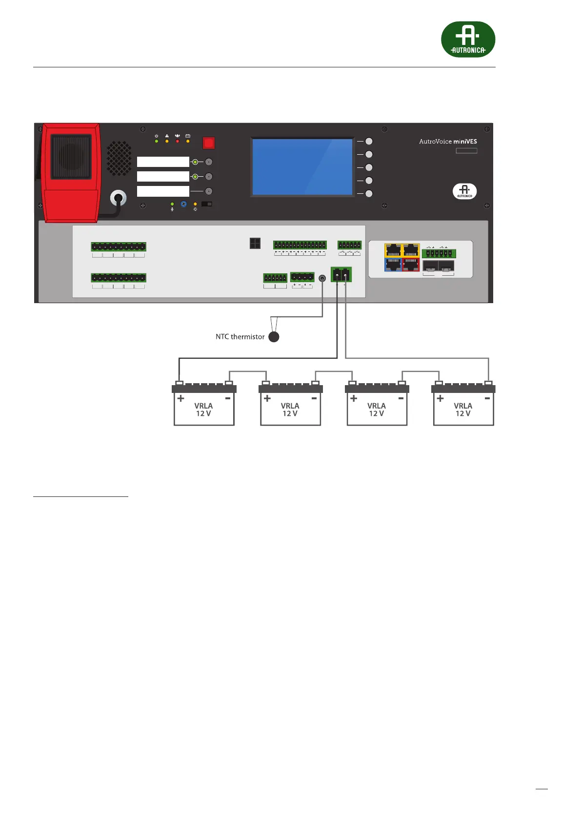
Battery connection diagram
Thermistor installation:
A thermistor, attached to a 3.5mm jack on the connector panel of the AutroVoice miniVES unit is intended to compensate tem-
perature changes when charging batteries. Placethe thermistor between two batteries.
NOTE: the thermistor cable can be extended by several meters without any risk of communication loss
Before powering up the AutroVoice miniVES unit for the rst time, it is necessary to perform standard inspections specied in the
chapter – Maintenance and service – page 77.
 Loading...