72
COMPACT VOICE ALARM SYSTEM
SERVICE MANUAL
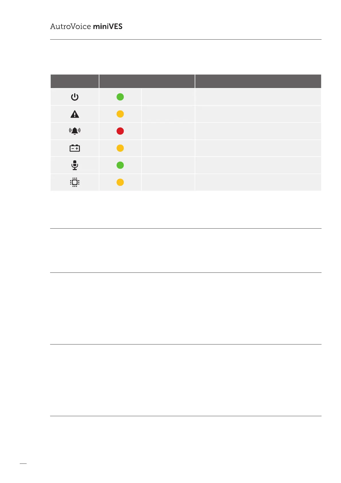
Table 16. LED colors on the control unit front panel
Graphic symbol Color AutroVoice miniVES Control Units
green POWER
yellow FAILURE
red ALARM
yellow Battery power active
green Handheld microphone active
yellow CPU-o function active (CPU bypass)
8.1 Normal mode
Power-on LED emits green light. In normal mode (no failure and locks) none of the LEDs in VASCU system emits yellow or red light.
8.2 Alarm mode
In this mode, all devices which are unnecessary during alarm (e.g. zone microphones, other devices which use structural network)
are automatically disconnected.
An LED marked as ALARM emits red light on the reman microphone, zone microphone and on the front panel of the Control
Unit. Fire scenario is carried out. Any activities are recorded in the event log.
8.3 Failure mode
In case of damage related to one of the system modules, the system enters failure mode, and information about failure is displayed
in the Control Unit and microphones. FAILURE yellow LED lights up. If the microphone has a button programmed as “conrm
failure” the built in speaker also signals the failure. When failure is signaled, press the button marked as “conrm failure” to mute
the alarm, the system will detect that the failure has just been accepted/conrmed by the Operator (this event is recorded in the
event log). The failure LED goes out when the system damage is eliminated and “Failure delete” button is pressed.
8.4 Lock mode
VASCU can lock and unlock sound system zones. In the locked zone, no messages are played back until unlocked.
When the zone is locked, the LED indicator emits yellow color on every microphone.
 Loading...