21
6.1.1.2 AutroVoice miniVES series 2001N, 4001N, 4002N
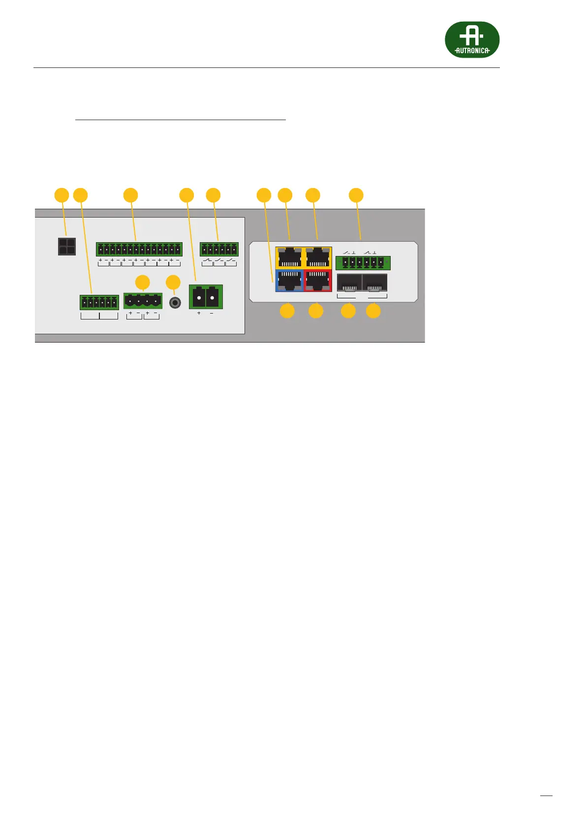
Units similar to the 2001, 4001, 4002 series with the exception of the extended xNET_mini 1GB/WAN/RS network interface.
Thisprovides more connectivity and slots for two optional SFP modules.
Drawing 2.
118 13 14
12
LAN/WANRS485
LANLAN PoE
IN1IN2
BA
FIBER
1
4 5
3 76 98 102
BUS1 BUS2
IN7IN6IN5IN4IN3IN2IN1
+48 VDC BATT
Audio IN Audio OUT
C
LR
C
LR
+24 VDC
150 mA
+48 VDC
350 mA
TEMP.
SENSOR
OUT3OUT2OUT1
Diagram of the connector panel for AutroVoice miniVES series 2001N, 4001N and 4002N units
1. Local audio bus outputs for 4 line control card operation
2. Audio input and output
3. Logic inputs
4. Auxillary power outputs
5. Battery temperature sensor input jack
6. Main Battery connector
7. Logic outputs
8. 10/100 Mbps Lan/Wan port (PC connection )
9. 10/100/1000 Mbps Lan port
10. 10/100/1000 Mbps Lan port
11. RS485 Port
12. Additional Logic I/O ports
13. SFP module slot B
14. SFP module slot A
3.
 Loading...