47
1. Microphone
2. LED indicators for: Power [green] (Power), Failure [yellow] (Fault), Evacuation [red] (EVAC)
3. Active microphone LED – the LED signals that the device is ready to transmit a voice message, if a gong is programmed,
themicrophone activates shortly after the sound is emitted
4. Functional buttons – freely programmable
5. LED indicators for functional buttons
6. “Push to talk” button – the button is programmed in order to activate microphone
7. Built-in loudspeaker
8. Buton description card slot
11.
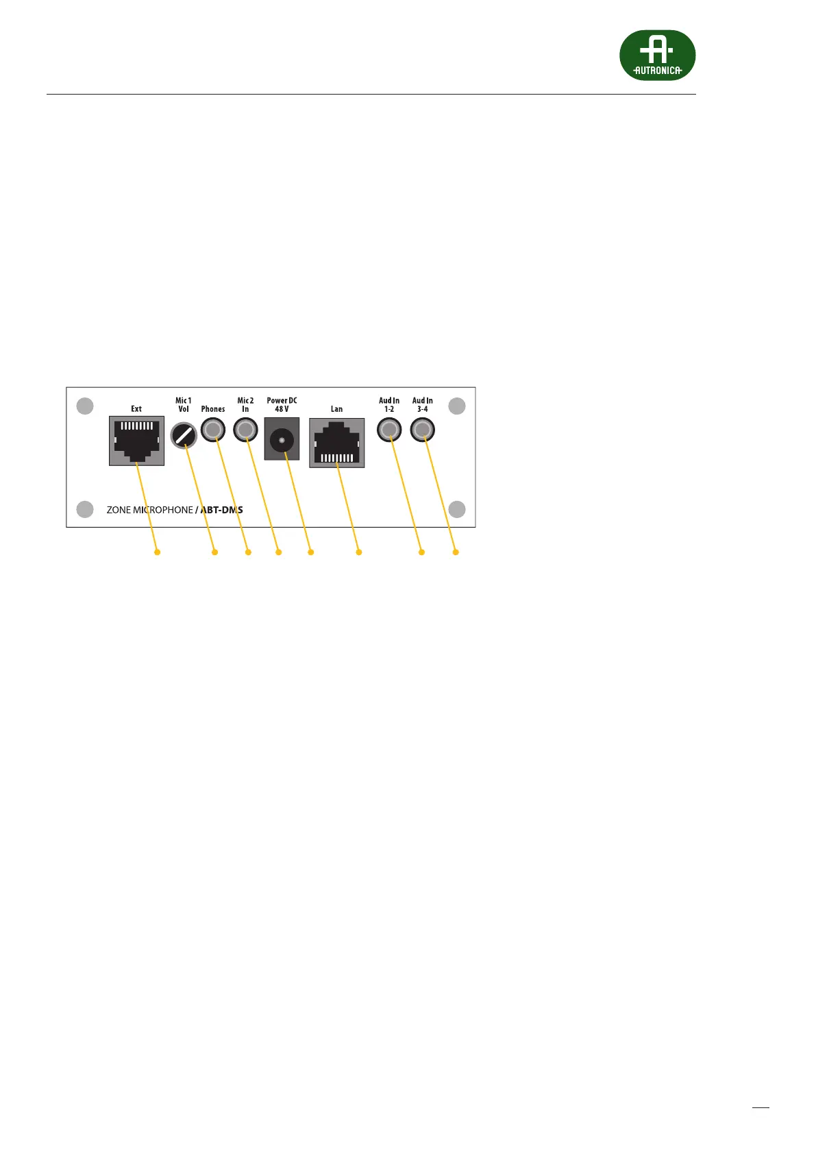
Drawing 25.
5 6 7 81 2 3 4
ABT-DMS zone microphone connectors diagram
1. RJ45 socket to connect microphone extension ABT-EKB-20M
2. Digital potentiometer
3. Headset 1/8'' jack socket
4. Headset mic 1/8'' jack socket
5. Power point 48V
6. Communication port providing connection with the control unit with the possibility to recieve PoE when connected
tothe ABT-xNet_mini series cards
7. 2 Audio inputs
8. 2 Audio inputs
 Loading...