58
COMPACT VOICE ALARM SYSTEM
SERVICE MANUAL
7.3.1 Control units
This section presents examples of control units connection diagrams.
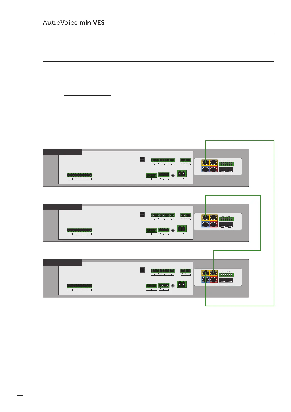
7.3.1.1 Daisy Chain Topology
In CHAIN topology, the connection is not redundant. Connecting units in this system does not guarantee operation of the system
in the event of communication cable damage. According to EN 54-16 norm, connections between VAS control units in a large
scale system must be redundant. Connections in CHAIN Topology are applied locally, and in the systems not responsible for
sending evacuation messages.
Drawing 33.
BUS1 BUS2
IN7IN6IN5IN4IN3IN2IN1
+48 VDC BATT
Audio IN Audio OUT
C
LR
C
LR
+24 VDC
150 mA
+48 VDC
350 mA
TEMP.
SENSOR
LINE ALINE BLINE CLINE DHV AUDIO IN
C
H
C
H
C
H
C
H
C
H
LAN/WANRS485
LANLAN PoE
IN1IN2
BA
FIBER
1
AV miniVES 2001N
OUT3OUT2OUT1
BUS1 BUS2
IN7IN6IN5IN4IN3IN2IN1
+48 VDC BATT
Audio IN Audio OUT
C
LR
C
LR
+24 VDC
150 mA
+48 VDC
350 mA
TEMP.
SENSOR
LINE ALINE BLINE CLINE DHV AUDIO IN
C
H
C
H
C
H
C
H
C
H
LAN/WANRS485
LANLAN PoE
IN1IN2
BA
FIBER
1
AV miniVES 2001N
BUS1 BUS2
IN7IN6IN5IN4IN3IN2IN1
+48 VDC BATT
Audio IN Audio OUT
C
LR
C
LR
+24 VDC
150 mA
+48 VDC
350 mA
TEMP.
SENSOR
LINE ALINE BLINE CLINE DHV AUDIO IN
C
H
C
H
C
H
C
H
C
H
LAN/WANRS485
LANLAN PoE
IN1IN2
BA
FIBER
1
AV miniVES 2001N
OUT3OUT2OUT1
OUT3OUT2OUT1
Example of CHAIN topology control units connection
 Loading...