101
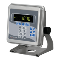
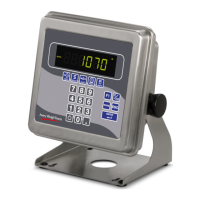
Model E1070 Indicator Service Manual
15. Press the SELECT key. . .
PORT1 is displayed.
16. Press the UNITS key. . .
PORT 2 is displayed. Repeat steps 11 and 12 to test port 2.
17. Press SELECT key. . .
SERIAL is displayed.
18. Press the UNITS key. . .
INPUT is displayed. This is the input test item.
19. Press the PRINT key to access the test.
1 2 3 is displayed. 1 stands for input 1, etc.
20. If you jumper pins 1 and 2 of the I/O connector on the bottom of the
indicator. . .
1 becomes 0 until the jumper is removed.
To test input 2, jumper pins 1 and 3. 2 becomes 0 until the jumper
is removed.
To test input 3, jumper pins 1 and 4. 3 becomes 0 until the jumper
is removed.
21. Press the SELECT key. . .
INPUT is displayed.
22. Press the UNITS key. . .
OUTPUT is displayed. This is the output test item.
23. Press the PRINT key to access the test.
OUT 1 is displayed. This stands for output 1.
24. Press the PRINT key. . .
The display toggles between ON and OFF. This will toggle the
output off and on. Monitor the output to see that it is turning off
and on. Use a Trips Interface Unit (TIU3) or other output device.
25. Stop the test by pressing the SELECT key. . .
OUT 1 is displayed.
26. Press the UNITS key. . .
OUT 2 is displayed.
27. Repeat steps 23 and 25 for outputs 2 and 3. . .
28. Press the SELECT key. . .
OUTPUT is displayed.
OUTPUT
(Output test)
INPUT
(Input test)
Supervisor Menu—(continued)
 Loading...