11-3
Chapter 11. SPECIFICATIONS
Display range lower limit: 0.0Aac
Display range upper limit: 70.0Aac (800 turns, 1 time)
Formula; Number of turns ÷ (16 x number of power wire loops) x 1.4
Display accuracy: ±5%FS
Display resolution: 0.1Aac
● RS-485 communication
Transmission line: 3-wire method
Transmission speed: 4800, 9600, 19200, 38400 bps
Communication distance: Max. 500m
CPL/MODBUS: Half duplex, start/stop synchronization method
Communication protocol: In conformity with CPL and MODBUS
Number of connection units: Max. 31 units
Terminating resistor: Connection prohibited.
● Loader communication
Transmission line: 3-wire method
Transmission speed: Fixed at 19200 bps.
Recommended cable: Specially designed cable, 2m Model No.: 81440793-001
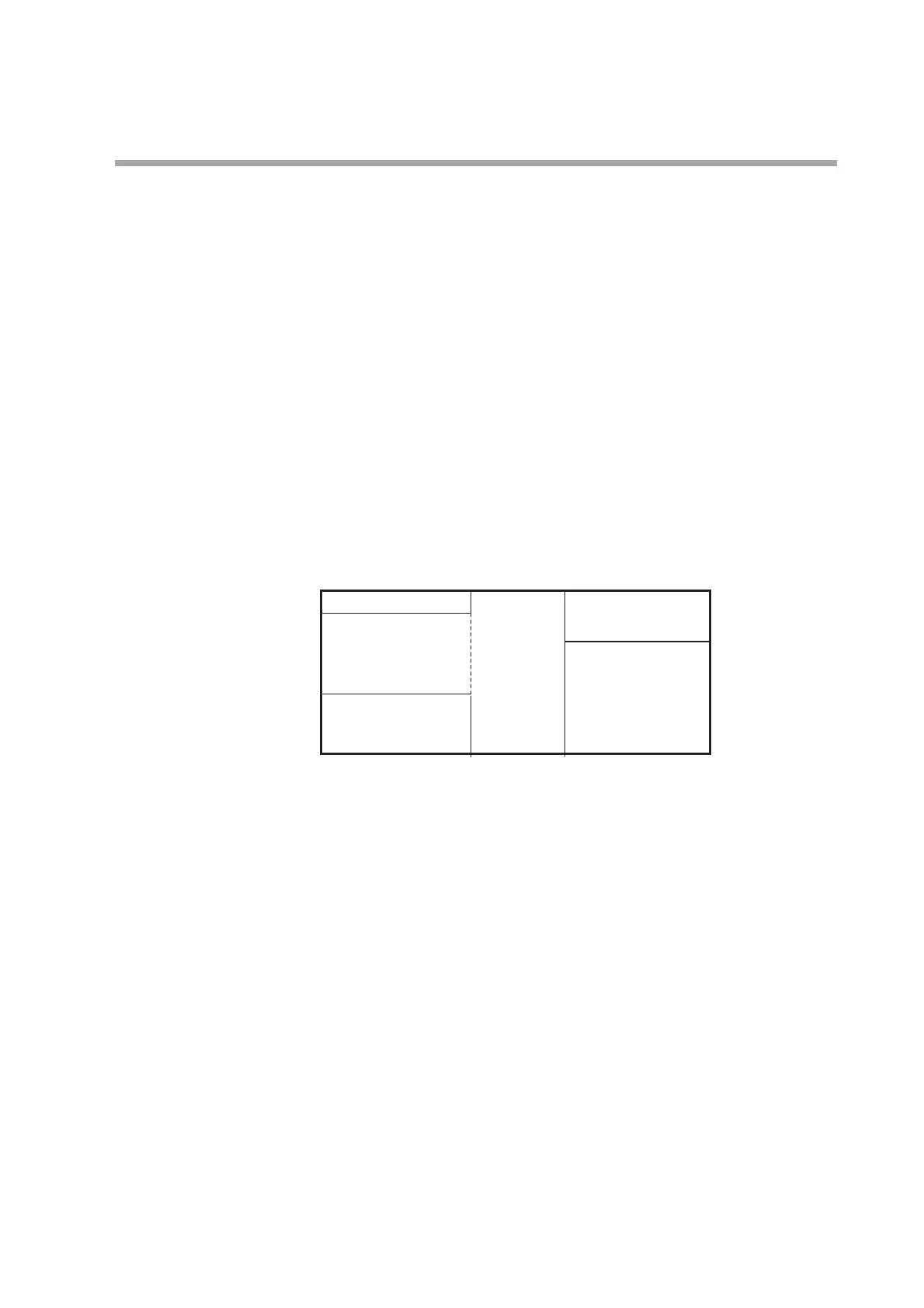
● Isolation between input and output
Portions enclosed by solid lines are insulated from other signals.
Whether or not inputs and outputs are provided may vary depending on the model.
✽ In case of the independent contacts, the output 1 and the output 2 are isolated.
● Environment conditions
• Standard conditions
Ambient temperature: 23±2˚C
Ambient humidity: 60±5%RH
Power supply voltage: AC power model, 105Vac±1%, 50/60Hz±1Hz
DC power model, 24Vac±1%, 50/60Hz±1Hz
24Vdc±5%
Vibration: 0m/s
2
Shock: 0m/s
2
Mounting angle: (Reference plane) ±3˚
• Operating conditions
Ambient temperature: 0 to 50˚C (0 to 40˚C for tight-mounting)
Ambient humidity: 10 to 90%RH (No condensation allowed.)
Power supply voltage: AC power model, 85 to 264Vac, 50/60Hz±2Hz
(Rating: 100 to 240Vac, 50/60Hz)
DC power model, 21.6 to 26AVac, 50/60Hz±2Hz/21.6 to 52.8Vdc
(Rating: 24Vac, 50/60Hz 24 to 48Vdc)
Vibration: 0 to 2m/s
2
(10 to 60Hz for 2 hrs. in each of the X-, Y-, and Z-direction)
Shock: 0 to 10m/s
2
Mounting angle: (Reference plane) ±10˚
Power supply Control output 1
PV input Control output 2
CT input 1 Internal circuit
CT input 2 Event output 1 ✽
Loader communication Event output 2 ✽
Digital input 1 Event output 3
Digital input 2
RS-485 communication