20
microspeed® uni motor system
Aesculap Power Systems
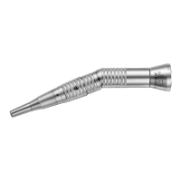
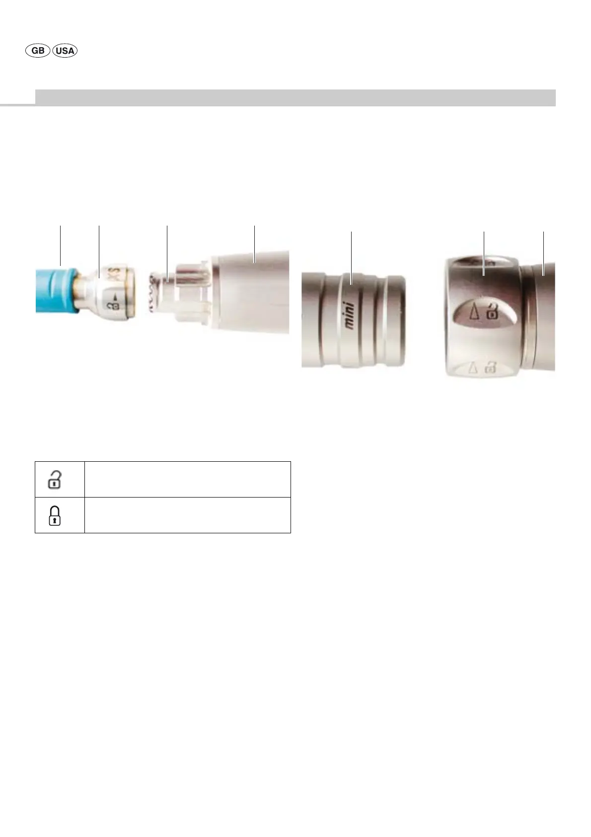
Connecting Hi-Line XS handpieces to high-speed motors GD676 and
GD677
Fig. 17
Legend
A Handpiece
B Threaded ring
C Handpiece coupling
32 Motor
Coupling:
¾ Turn threaded ring B of handpiece A in the direction indicated by the
arrow in symbol “Handpiece release” as far as it will go.
¾ Install handpiece A on handpiece coupling C of motor 32 in such a way
that the pin on the handpiece engages in one of the notches of the
handpiece coupling.
¾ Turn threaded ring B in the direction indicated by the arrow in symbol
“Handpiece locking” as far as it will go.
¾ Make certain that threaded ring B is tightened to its limit stop to
prevent it from coming loose due to vibrations during operation.
Uncoupling:
¾ Turn threaded ring B in the direction indicated by the arrow in symbol
“Handpiece release” as far as it will go.
¾ Detach handpiece A from motor 32.
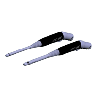
Connecting mini-Line attachments to microspeed® uni mini 100
motor GD674 and microspeed® uni mini pistol handpiece GD684
Fig. 18
Legend
A mini-Line attachment
B Tension ring
C Motor drive
Coupling:
¾ Turn tension ring B on motor C in the “open” direction as indicated by
the arrow, as far as it will go.
¾ Push the coupling of mini-Line attachment A into tension ring B at
motor C as far as it will go.
¾ Turn tension ring B on motor C against the “open” direction as
indicated by the arrow, as far as it will go.
Uncoupling:
¾ Turn tension ring B on motor C in the “open” direction as indicated by
the arrow, as far as it will go.
¾ Retract mini-Line attachment out of tension ring B at motor C.
¾ If tension ring B on the coupling cannot be loosened by hand, use the
auxiliary wrench of motor C.
Symbol “Handpiece release”
Symbol “Handpiece locking”
CB 32A
A B C