Power connections Page 10/51
MID_M2000_BA_02_1807
4.2 Separate version
Caution: • Connect or separate signal connection cable only when the unit has been
switched off.
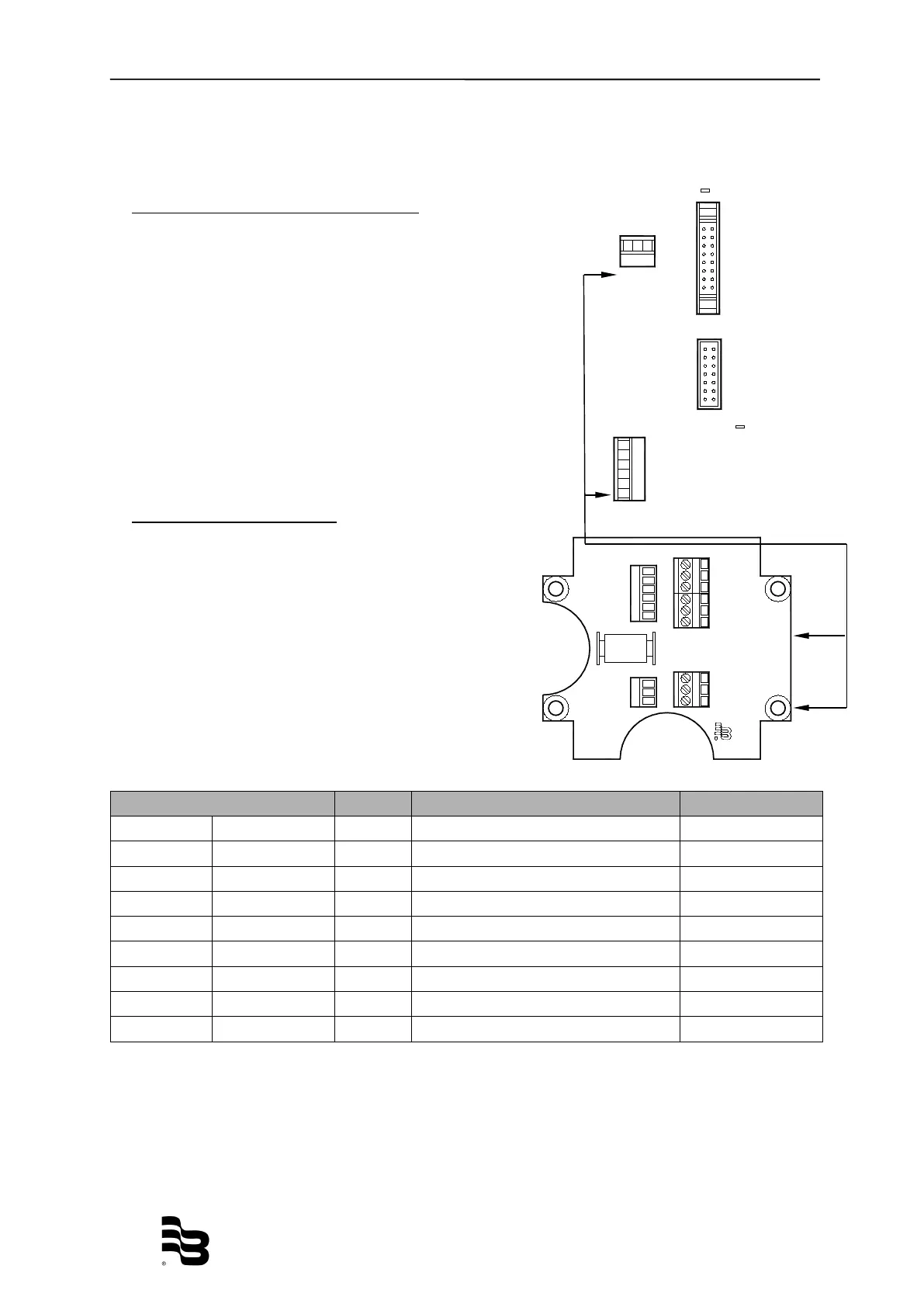
Connection in the measuring amplifier
1. Loosen both fixing screws of the connection cover and
remove cover.
2. Loosen upper and lower cover screw and open cover
to the left side.
3. Push signal cable on the upper side of the device
through cable inlet.
4. Connection as shown in the picture.
5. Close device and connection cover again firmly.
Connection on the detector
1. Loosen fixing screws of the connection cover
and remove cover.
2. Push signal cable through cable inlet.
3. Connection as shown in the picture.
4. Close device and connection cover again
firmly.
*) Connections with number 44 are on the same potential.
5MID
13 Shield
12 C2
11 C1
44 Shield
40 EP
44 Shield
46 E2
44 Shield
45 E1
Display
Calibrator
TP2
TP21
BA16MID
R
Badger Meter
JBOX - PRIMO
REMOTE - REV1
From
Detector
To Amplifier
11 COIL
12 COIL
13 SHIELD
COIL 11
COIL 12
Shield 13
Shield 44
Shield 44
SHIELD 44
ELECTRODE 45
ELECTRODE 46
EMPTY PIPE 40
44 SHIELD
44 Shield
44 Shield
40 EMPTY PIPE
46 ELECTRODE
45 ELECTRODE