EasyManuals Logo

Badger Meter ModMAG M2000 User Manual

Badger Meter ModMAG M2000
56 pages
To Next Page IconTo Next Page
To Previous Page IconTo Previous Page
Page #8 background imageLoading...
Page #8 background image
Installation Page 6/51
MID_M2000_BA_02_1807
max.8°
BA2000-15-MID
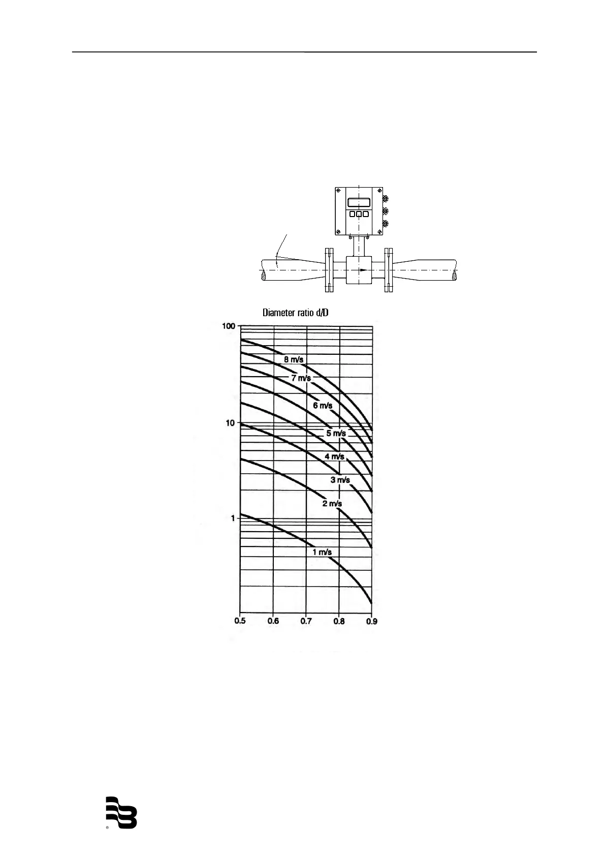
3.2.4 Pipe reducer requirements
With pipe reducers as per DIN 28545 detectors can be mounted in larger pipelines.
You can determine the occurring pressure drop by using the shown nomogram (only
applicable to liquids with similar viscosity like water).
Note: In cases where flow velocities are very low, you can increment them by
reducing the size on the measuring point and hence obtain a better
measuring accuracy.
Define pressure loss:
1. Calculate diameter ratio d/D.
2. Read pressure loss depending on d/D ratio and flow velocity.
D = pipeline
d = detector
Pressure loss in mbar

Other manuals for Badger Meter ModMAG M2000

Questions and Answers:

Question and Answer IconNeed help?

Do you have a question about the Badger Meter ModMAG M2000 and is the answer not in the manual?

Badger Meter ModMAG M2000 Specifications

General IconGeneral
Flow Measurement TechnologyElectromagnetic
Enclosure RatingNEMA 4X (IP66)
Repeatability±0.1% of rate
Output4-20 mA, pulse, frequency
DisplayLCD with backlight
Power Supply100 to 240 VAC or 24 VDC
Communication ProtocolsHART, Modbus
Process ConnectionFlanged, Threaded
Electrode Material316 Stainless Steel, Hastelloy, Tantalum
Liner MaterialPTFE, PFA, Polyurethane
Accuracy±0.2% of rate
Temperature Range-40°...160°F (-40°...71°C)
Fluid Temperature-4°...302°F (-20°...150°C)
MaterialsStainless Steel, Carbon Steel

Related product manuals