Power connections Page 12/51
MID_M2000_BA_02_1807
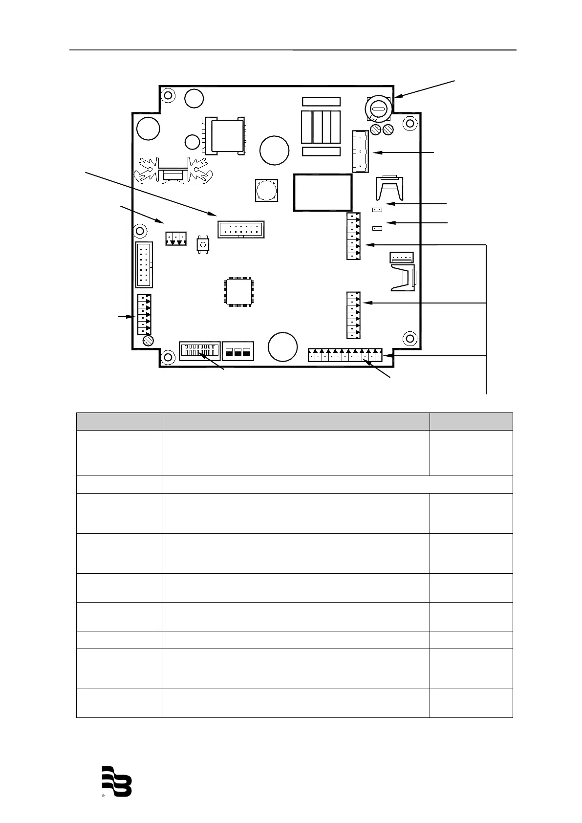
BA2000-22MID
L N PE
JP1
JP2
C
OMMUNICATION
DISPLAY
CS
C2
C1
E1
ES
E2
RS
EP
ES
15
16
1
2
3
4
5
6
7
8
9
10
11
12
13
14
4.3 Configuring input/output (I/O)
Displ
Input/Output Description Terminal
Analog output
4 - 20 mA RL < 800 Ohm
0 - 10 mA
16 (+)
15 (-)
Digital output
1 Open collector max. 10 kHz
* Passive max. 30 VDC, 100 mA
* Active 24 VDC, 50 mA (Jumper JP1 placed)
1 (+) and 2 (-)
2 Open collector max. 10 kHz
* Passive max. 30 VDC, 100 mA
* Active 24 VDC, 50 mA (Jumper JP2 placed)
3 (+) and 4 (-)
3 Open collector passive max. 30 VDC, 100 mA, max. 10 kHz
or Solid State Relais max. 48 VAC, 500 mA, max 1 kHz
10 (+) and 11 (-)
10 and 11
4 Open collector passive max. 30 VDC, 100 mA, max. 10 kHz
or Solid State Relais max. 48 VAC, 500 mA, max 1 kHz
13 (+) and 14 (-)
13 and 14
Digital input 5 - 30 VDC 8 (+) and 9 (-)
RS 232 Remote display information or
Modbus RTU
7 GND
6 RxD
5 TxD
Communication Optional communication ports like
HART, Profibus DP, ModBus
®
RS 485, M-Bus
Communication