EasyManuals Logo

Badger Meter ModMAG M2000 User Manual

Badger Meter ModMAG M2000
56 pages
To Next Page IconTo Next Page
To Previous Page IconTo Previous Page
Page #7 background imageLoading...
Page #7 background image
Installation Page 5/51
MID_M2000_BA_02_1807
BA2000-11-MID
h > 2 x DN
BA2000-12-MID
> 3-5 x DN
> 2 x DN
BA2000-13-MID
BA2000-14-MID
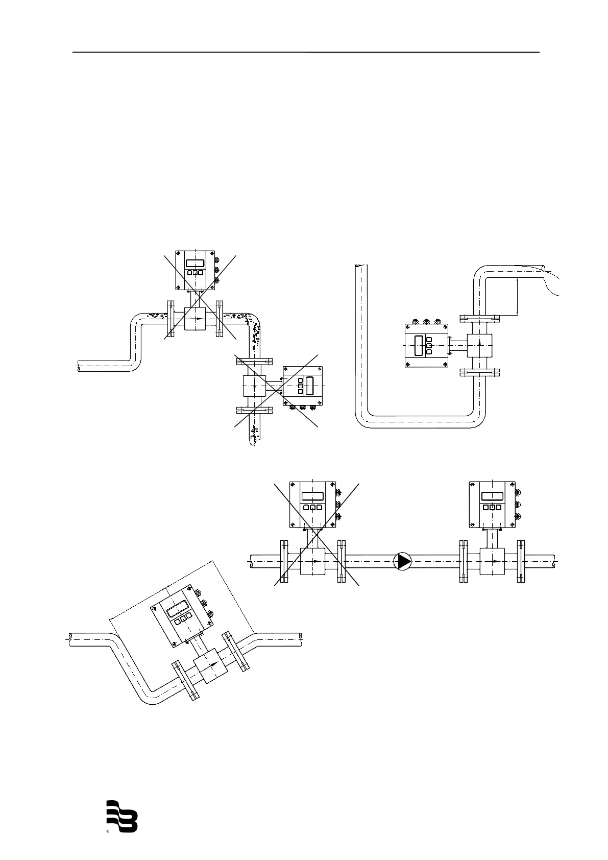
3.2.3 Meter location
Caution: Do not install the detector on the suction sides of pumps. This could
damage the liner (in particular PTFE liners).
Verify that the pipeline is always filled on the measuring point, if not - a
correct or accurate measurement is not possible.
Do not install the detector on the highest point of a pipeline system. Gas
accumulation may follow.
Do not install the detector in downcomer pipes with free outlet.
Do not install the detector on pipes with vibrations. If pipes are strongly
vibrating, make sure that detector and amplifier are separated (separate
version).

Other manuals for Badger Meter ModMAG M2000

Questions and Answers:

Question and Answer IconNeed help?

Do you have a question about the Badger Meter ModMAG M2000 and is the answer not in the manual?

Badger Meter ModMAG M2000 Specifications

General IconGeneral
Flow Measurement TechnologyElectromagnetic
Enclosure RatingNEMA 4X (IP66)
Repeatability±0.1% of rate
Output4-20 mA, pulse, frequency
DisplayLCD with backlight
Power Supply100 to 240 VAC or 24 VDC
Communication ProtocolsHART, Modbus
Process ConnectionFlanged, Threaded
Electrode Material316 Stainless Steel, Hastelloy, Tantalum
Liner MaterialPTFE, PFA, Polyurethane
Accuracy±0.2% of rate
Temperature Range-40°...160°F (-40°...71°C)
Fluid Temperature-4°...302°F (-20°...150°C)
MaterialsStainless Steel, Carbon Steel

Related product manuals