R5911692 /01 MDSC-8231 13
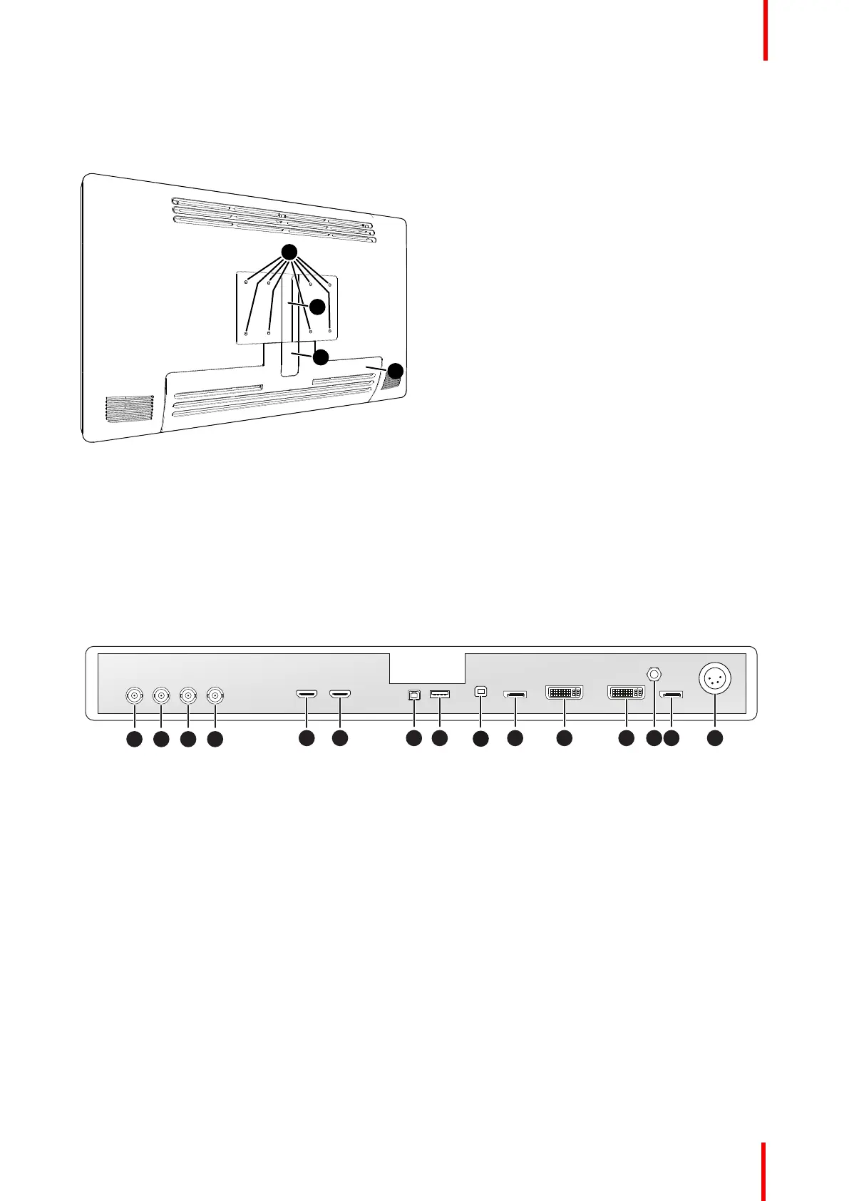
2.2 Rear view
Overview
Image 2-2
1. VESA mount screw holes (100 x 100 mm, 200 x 100 mm)
2. Cable routing channel
3. Cable routing channel expansion clip
4. Connector compartment cover
2.3 Connector view
Overview
2 3 4
7 8 10 14 1511 12 13
1
5 6
9
Image 2-3
1. SDI 1: Single link in or Quad link in top left
(*)
2. SDI 2: Single link out or Quad link in top right
(*)
3. SDI 3: Single link in or Quad link in bottom right
(*)
4. SDI 4: Single link out or Quad link in bottom left
(*)
5. HDMI 2 in
6. HDMI 1 in
7. +5 VDC – 2 A power out
8. USB 2.0 type A interface
9. USB 2.0 type B interface
10.Main (Right) DisplayPort in
11. DVI-D in
12.DVI-D out
13.Potential Equalization pin (POAG)
14.2
nd
(Left) DisplayPort in
15.24 VDC power in
(*)
The BNC SDI connectors match the characteristic impedance of 75 ohm cables. See “SDI config”, page 35
about the possible SDI configuration modes.
Parts, controls and connectors
 Loading...