R5911692 /01 MDSC-823118
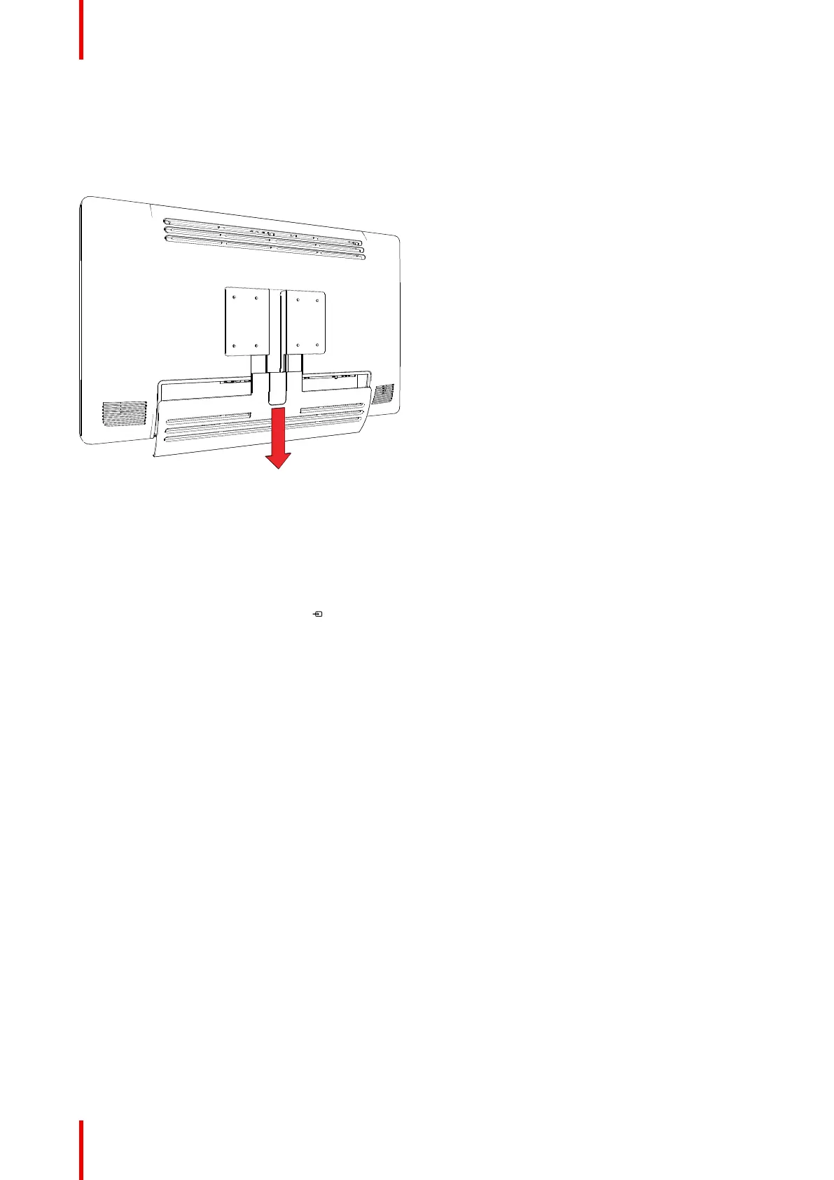
3.1 Cover removal
To remove the connector compartment cover
Slide the connector compartment cover downwards to get access to the connectors.
Image 3-1
3.2 Interface connection
About
The MDSC-8231 can have multiple video inputs connected. Switching between the different inputs can be
done easily with the Source shortkey (
).
Futhermore, if more than one video source is connected, the Picture in Picture and Picture and Picture (PiP/
PaP) functionalities become available, allowing you to view 2 different video inputs at once. Refer to “Picture
and Picture input”, page 37 and “Picture in Picture input”, page 38 for more information.
Beside the video input connections, the MDSC-8231 also has video output capabilities allowing you to loop-
through or duplicate all video inputs connected with the MDSC-8231 to another display, projector, video
recorder, ...
This chapter describes how to connect the different video interface types to the MDSC-8231.
To connect the interfaces
1. Connect one or more video source(s) to the corresponding video inputs of the display. For a list of
supported video inputs, see “Technical specifications”, page 60. See “SDI config”, page 35 about the
possible SDI configuration modes.
2. Screen image clone: The entire active image on the screen (including OSD) can be duplicated to a FHD
(1080p/1080i) signal on the DVI output connector, to which an additional DVI video sink can be connected.
3. Connect the USB2.0 type B interface with a workstation to use the remote control protocol, to update the
display firmware, or to be able to connect any USB peripheral with the USB interfaces of the display.
4. Use any USB peripheral (keyboard, mouse, webcam, ...) by connecting it to the available USB interfaces.
5. Connector +5 VDC - 2A power out for accessory (Mating connector HIROSE RP34L-5PA- 2SC(1857)(71)).
Installation
 Loading...