R5911692 /01 MDSC-823114
2.4 Connector pin assignments
2.4.1 Input power connector
Overview
Image 2-4
1. +24 VDC
2. +24 VDC
3. GND
4. GND
CAUTION: The ground and the shield connections on the power input connector have no Protective
Earth function. A Protective Earth connection is provided via a dedicated pin (see “Power supply
connection”, page 19).
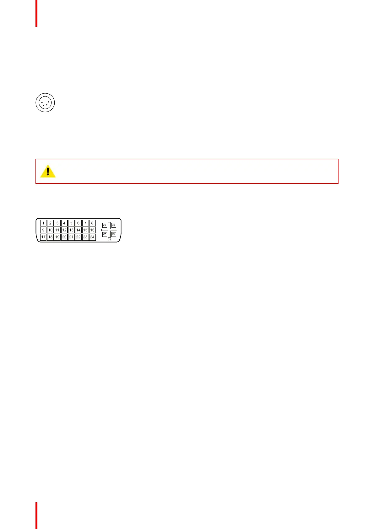
2.4.2 DVI connector (DVI-D)
Overview
Image 2-5
1. D2_Rx- (T.M.D.S.)
2. D2_Rx+ (T.M.D.S.)
3. GND (data 2 shield)
4. Not connected
5. Not connected
6. SCL (for DDC)
7. SDA (for DDC)
8. Not connected
9. D1_Rx- (T.M.D.S.)
10.D1_Rx+ (T.M.D.S.)
11. GND (data 1 shield)
12.Not connected
13.Not connected
14.+5V output (*)
15.GND (cable sense)
16.Hot plug detect (*)
17.D0_Rx- (T.M.D.S.)
18.D0_Rx+ (T.M.D.S.)
19.GND (data 0 shield)
20.Not connected
21.Not connected
22.GND (clock shield)
23.CK_Rx+ (T.M.D.S.)
24.CK_Rx- (T.M.D.S.)
(*) +5 VDC output selectable on either pin 14 or 16 via the OSD menu. (+5V ± 10% @ 500mA (max))
Parts, controls and connectors

 Loading...