10-35
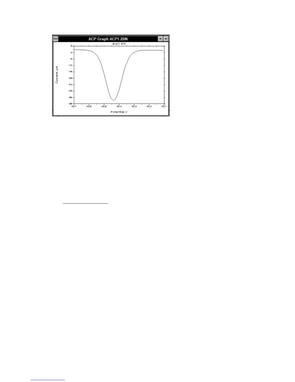
Figure 10-21.
A.C. current response for
ACV/P.
The phase angle for an ideal reversible system is 45
o
, whereas for quasi-reversible
systems (slow electron transfer), it is less than 45
o
. Since reversibility depends on the
timescale of the experiment, increasing the A.C. frequency often causes the behavior
of a system to change from reversible to quasi-reversible. A plot of the cotangent of
the phase angle vs. (frequency)
1/2
can be used to calculated the rate of electron
transfer.
The peak current, i
p
, for a reversible system is given by the equation:
i
nFAD C E
RT
p
=
2 2 12 12
4
//
∆ω
where: n = number of electrons transferred/mole
F = Faraday constant, 96500 C/mole
A = electrode surface area (cm
2
)
D = diffusion coefficient (cm
2
/s)
C = concentration (mol/cm
3
)
∆
E = peak to peak amplitude of A.C. potential
ω
= 2
π
(A.C. frequency)
As the system changes from reversible to quasi-reversible (and then to irreversible), i
p
decreases significantly, and is no longer proportional to
ω
1/2
(it was proposed at one
time that an irreversible process could not be detected by A.C. techniques; this is not
so, although the peak currents for such systems are small).
The A.C. current response to the A.C. potential is not linear; that is, it is a summation
of the fundamental and higher order frequencies. The second harmonic frequency
response (
SHACV/P
) is often used. The information gained by this technique is the
same as for
ACV/P
and
PSACV/P
; in addition, there is additional discrimination
against the charging current, and the timescale is shorter.
SHACV/P
has been used to