10-50
RPM
t
QUIET TIME
INIT
E
FINAL
t
B.A.
Figure 10-28.
Typical rotation rate (A) and potential wave form (B) for
RDE
.
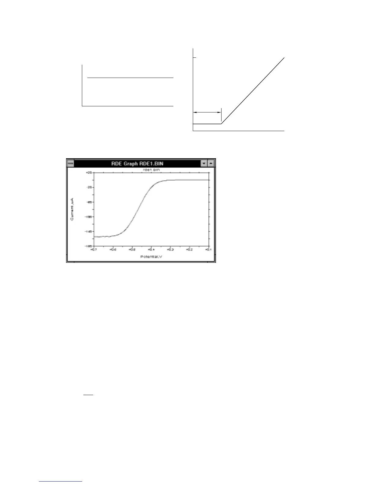
Figure 10-29.
Typical current response for
RDE
.
Hydrodynamic Modulation (
HDM
) is a related technique in which the frequency is
varied sinusoidally with time. More specifically,
ω
1/2
is varied, since i
l
is proportional
to
ω
1/2
. The A.C. current is handled using conventional data handling techniques; that
is, filtering followed by rectification or phase selective detection.
Consider the following example. According to the Levich equation, i
l
= K
ω
1/2
, where
ωω ω σ
12
0
12 12// /
sin
=+∆
t (
ω
o
is the base rotation rate that is modulated with a sine
waveform of frequency
σ
(
σ
= 2
π
f) and amplitude
∆ω
1/2
(Figure 10-30)). The A.C.
output is shown in Figure 10-31, and the processed I is shown in Figure 10-32.
∆
i is
given by the equation
∆
ii
=
ω
ω
ω
0
12
0
/