2-5
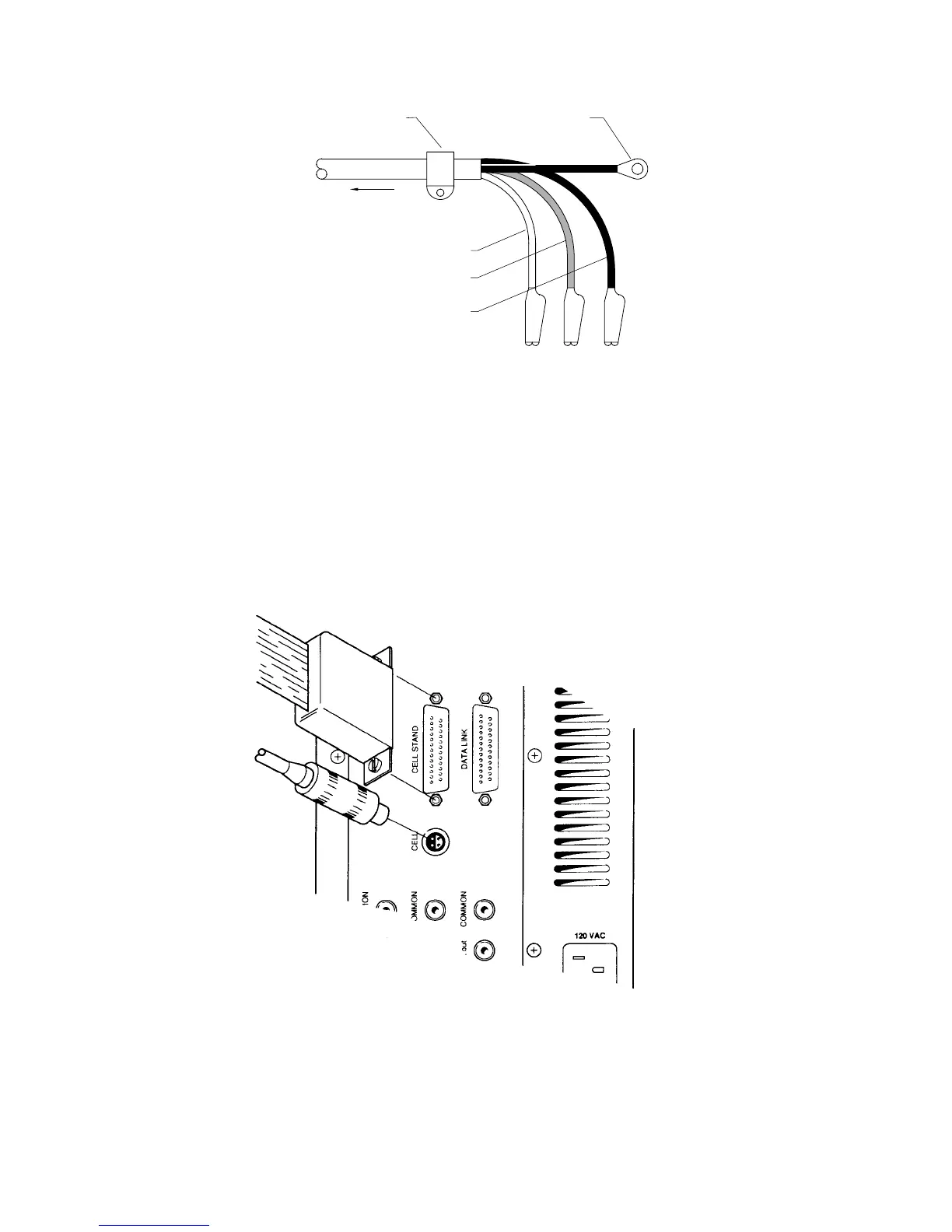
REFERENCE (WHITE)
AUXILIARY (RED)
WORKING (BLACK)
TO CELL CONNECTOR
ON BAS 100A
STRAIN RELIEF GROUND (BLACK)
Figure 2-3.
Cell (electrode) end of cell cable.
A plastic mounting lug near the end of the cell cable provides strain relief by
preventing movement of the line or cell.
Cell Stand Connector
This connector is used to control cell stand functions (i.e., stirring, gas purging
and drop knocking), and is plugged into the CELL STAND port on the rear panel
of the Analyzer (Figure 2-4).
Figure 2-4.
Attaching cell lead to BAS 100B.
There are 3 cell stand configurations available for the BAS 100B/W Workstation
(through
Setup
in the
File
menu). One configuration (
C2
) is for the BAS C2 Cell