Physical Interface AW00118303000
66 Basler racer GigE
Using the Outputs with LVTTL
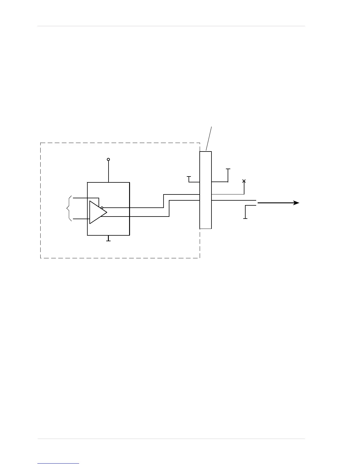
You can use a camera output line as an input to a low voltage TTL receiver, but only if the camera’s
output signal is used as shown in Fig. 22. In this situation, a low will be indicated by a camera output
voltage near zero, and a high will be indicated by a camera output voltage of approximately 3.3
VDC. These voltages are within the typically specified levels for low voltage TTL devices.
For the camera’s I/O circuitry to operate properly, you must supply a ground as shown in Fig. 22.
Fig. 22: Output Line Wired for Use with an LVTTL Input
7.6.2.2 Input Related Signals as Output Signals
The camera allows selecting the output signals of the shaft encoder module or of the frequency
converter module and assigning them to one of the camera’s digital output lines. In this fashion input
signals can be passed through a camera to trigger additional cameras.
In this case, setting a minimum output pulse width may be necessary to ensure output signal
detection.
For more information about selecting the source signal for an output line on the camera, see
Section 7.6.2.5 on page 68.
For more information about the electrical characteristics of the camera’s output lines, see
Section 7.6.2.1 on page 64.
For more information about the minimum output pulse width feature, see Section 7.6.2.3 on
page 67.

 Loading...


