AW00118303000 Physical Interface
Basler racer GigE 49
7 Physical Interface
This chapter provides detailed information, such as pinouts and voltage requirements, for the
physical interface on the camera. This information will be especially useful during your initial
design-in process.
7.1 General Description of the
Connections
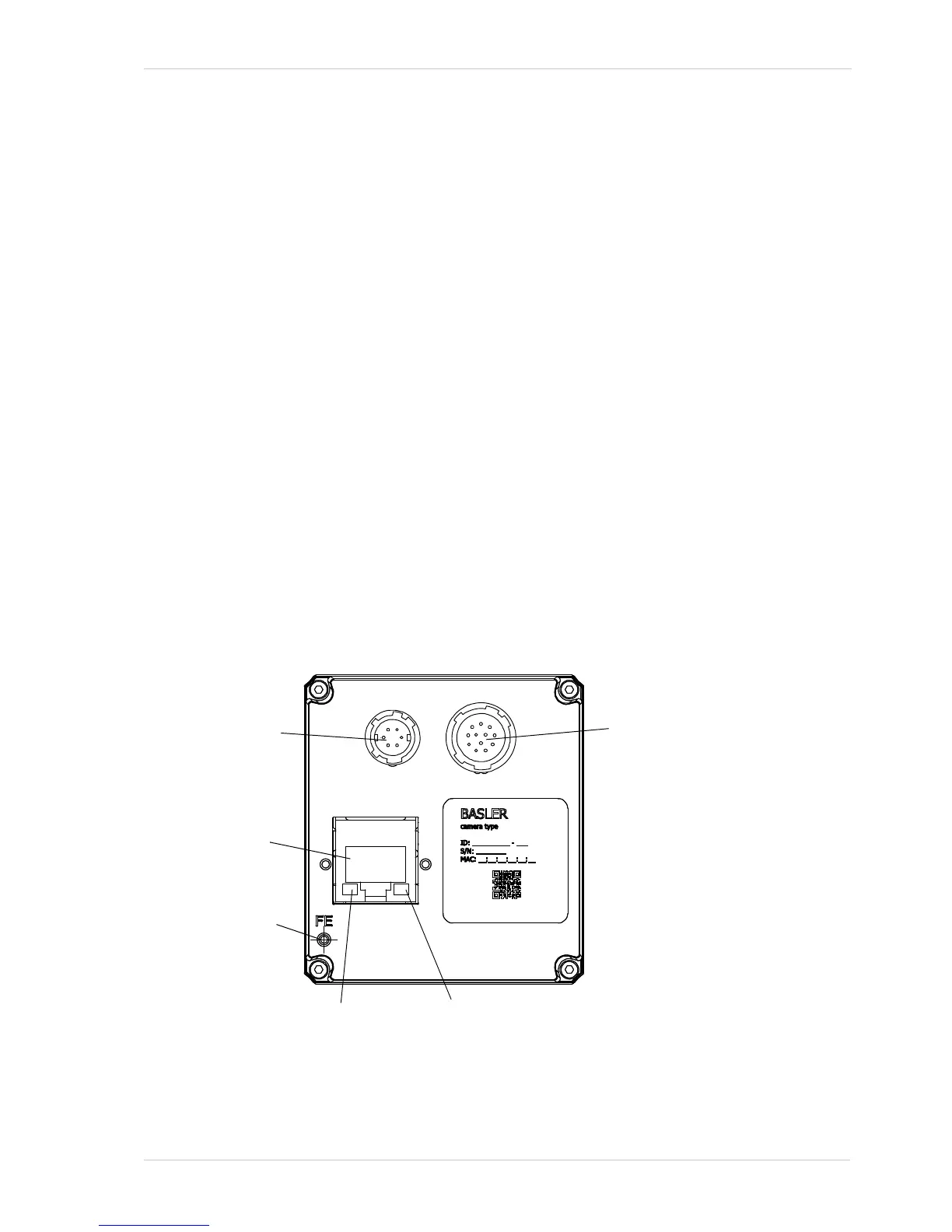
The camera is interfaced to external circuity via connectors located on the back of the housing:
A 6-pin receptacle used to provide power to the camera.
A 12-pin receptacle used to provide access to the camera’s I/O lines.
An 8-pin RJ-45 jack used to provide a 100/1000 Mbit/s Ethernet connection to the camera.
The jack includes a green LED and a yellow LED that indicate the state of the network
connection.
The drawing below shows the location of the three connectors, the LEDs, and the functional earth
connection.
Fig. 13: Camera Connectors , LEDs, and Functional Earth Connection

 Loading...


