AW00118303000 Physical Interface
Basler racer GigE 51
7.2 Connector Pin Assignments
7.2.1 Pin Assignments for the 6-pin Connector
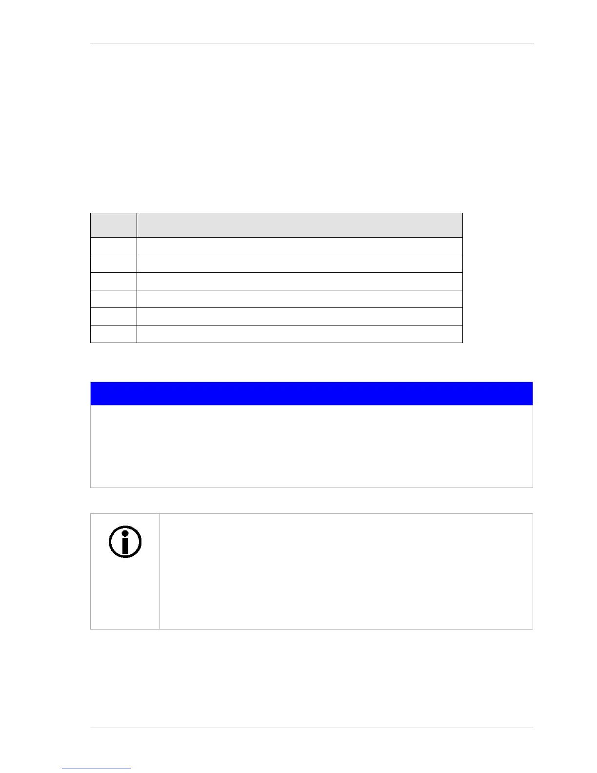
The 6 pin connector is used to supply power to the camera. The pin assignments for the connector
are shown in Table 5.
Pin Designation
1 +12 VDC (- 10 %) to +24 VDC (+ 5 %), < 1 % ripple, Camera Power *
2 +12 VDC (- 10 %) to +24 VDC (+ 5 %), < 1 % ripple, Camera Power * *
3 Not Connected
4 Not Connected
5 DC Ground **
6 DC Ground **
Table 5: Pin Assignments for the 6-pin Connector
NOTICE
Applying incorrect power can damage the camera.
The camera‘s nominal operating voltage is +12 VDC (± 10 %), effective on the camera‘s
connector.
Applying power with the wrong polarity can severely damage the camera.
Make sure that the polarity of the power applied to the camera is correct.
* Pins 1 and 2 are tied together inside the camera.
** Pins 5 and 6 are tied together inside the camera.
To avoid a voltage drop when there are long wires between your power supply and
the camera, we recommend that you provide +12 VDC through two separate wires
between the power supply and pins 1 and 2 in the receptacle. We also recommend
that you provide the ground through two separate wires between the power supply
and pins 5 and 6.

 Loading...


