Physical Interface AW00118303000
64 Basler racer GigE
7.6.2 Output Lines
The camera is equipped with two physical output lines designated as Output Line 1 and Output Line
2. The output lines are accessed via the 12-pin connector on the back of the camera. The outputs
are designed to transmit RS-422 differential signals, but they can also be used with RS-644 low
voltage differential signalling or low voltage TTL signalling.
7.6.2.1 Electrical Characteristics
Using the Outputs with RS-422
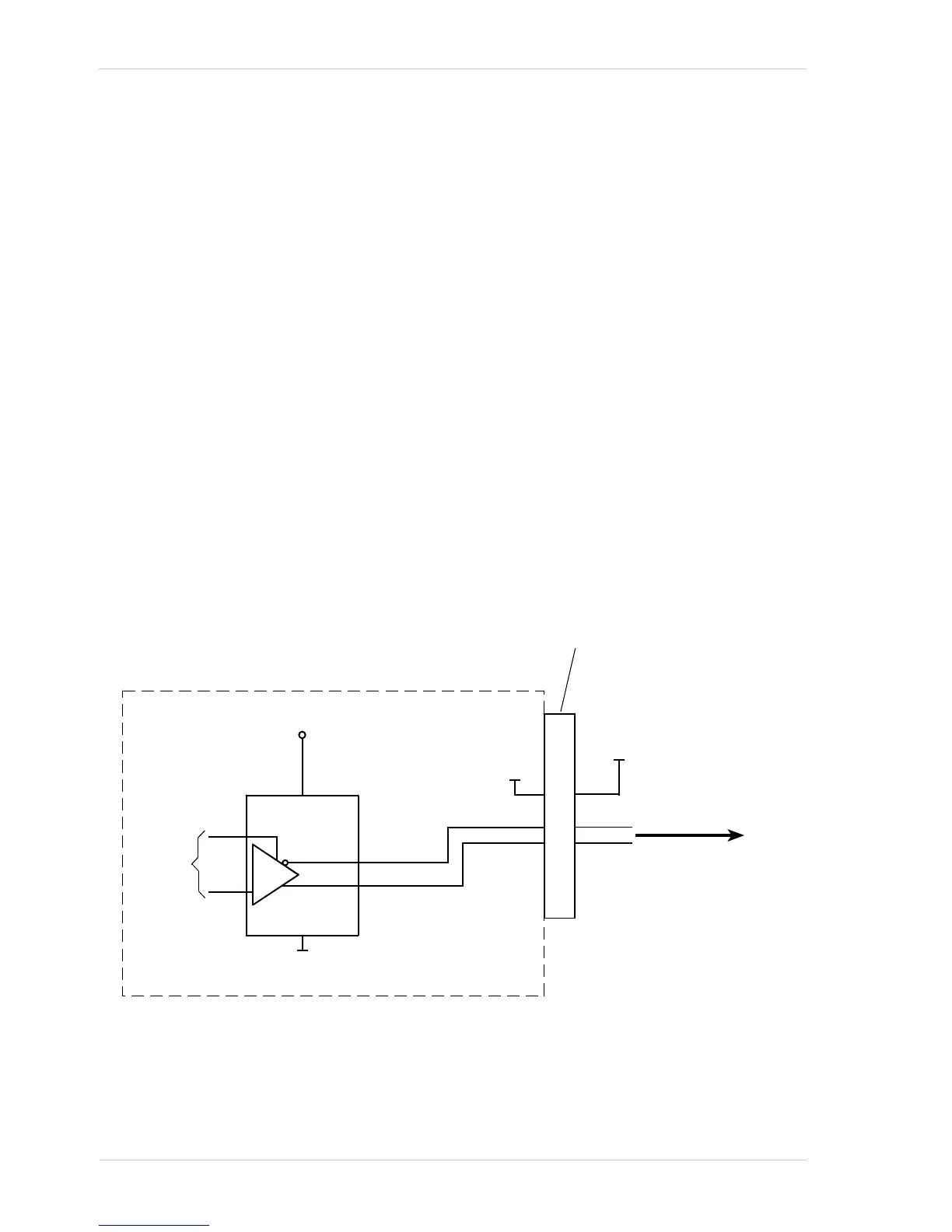
As shown in Fig. 20 and in the I/O schematic at the beginning of this section, each output is
designed to transmit an RS-422 signal. For the camera’s I/O circuitry to operate properly, you must
supply a ground as shown in Fig. 20.
The RS-422 standard allows devices to be used with a bus structure to form an interface circuit. So,
for example, output line 1 on a camera can be connected to an RS-422 bus in parallel with the inputs
on several of your devices (receivers). The camera with output line 1 connected to the bus would
serve as a "master" transmitter to the "slave" inputs of the other connected devices. For more
information about an RS-422 interface circuit and a related figure, see the "Using the Inputs with
RS-422" section.
Be aware that the last receiver in an RS-422 bus must have a 120 Ohm termination resistor.
Fig. 20: RS-422 Output Signal

 Loading...


