EasyManuals Logo

Basler GigE VISION CAMERAS User Manual

Basler GigE VISION CAMERAS
234 pages
To Next Page IconTo Next Page
To Previous Page IconTo Previous Page
Page #65 background imageLoading...
Page #65 background image
AW00118303000 Physical Interface
Basler racer GigE 57
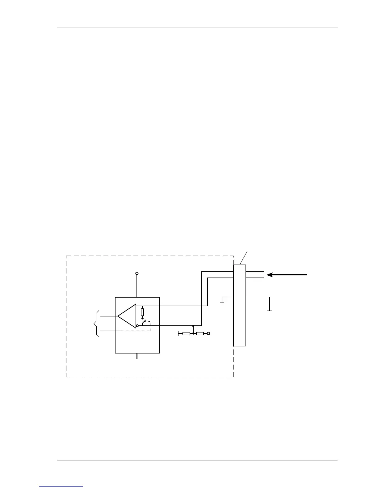
7.6 Input and Output Lines
7.6.1 Input Lines
The camera is equipped with three physical input lines designated as Input Line 1, Input Line 2, and
Input Line 3. The input lines are accessed via the 12-pin connector on the back of the camera. The
inputs are designed to accept RS-422 differential signals, but they can also be used with RS-644
low voltage differential signals or low voltage TTL signals.
7.6.1.1 Electrical Characteristics
Using the Inputs with RS-422
As shown in Fig. 17 and in the I/O schematic at the beginning of this section, each input is designed
to receive an RS-422 signal. For the camera’s I/O circuitry to operate properly, you must supply a
ground as shown in Fig. 17.
Fig. 17: Inputting RS-422 or RS-644 Signals
1
2
3
4
5
10
6
7
8
9
11
12
Camera
12-pin
Connector
I/O In 1 -
I/O In 1 +
3.3 V
120
To
FPGA
(control)
10
k
8.2
k
3.3 V
Gnd
Gnd
Your
Gnd
Your RS-422
or RS-644
Input Signal
RS-422
Transceiver
RS-422 Transceiver =
Linear Technology LTC 2855
or the equivalent
Receiver
Gnd

Table of Contents

Questions and Answers:

Question and Answer IconNeed help?

Do you have a question about the Basler GigE VISION CAMERAS and is the answer not in the manual?

Basler GigE VISION CAMERAS Specifications

General IconGeneral
BrandBasler
ModelGigE VISION CAMERAS
CategoryDigital Camera
LanguageEnglish

Related product manuals