Physical Interface AW00118303000
58 Basler racer GigE
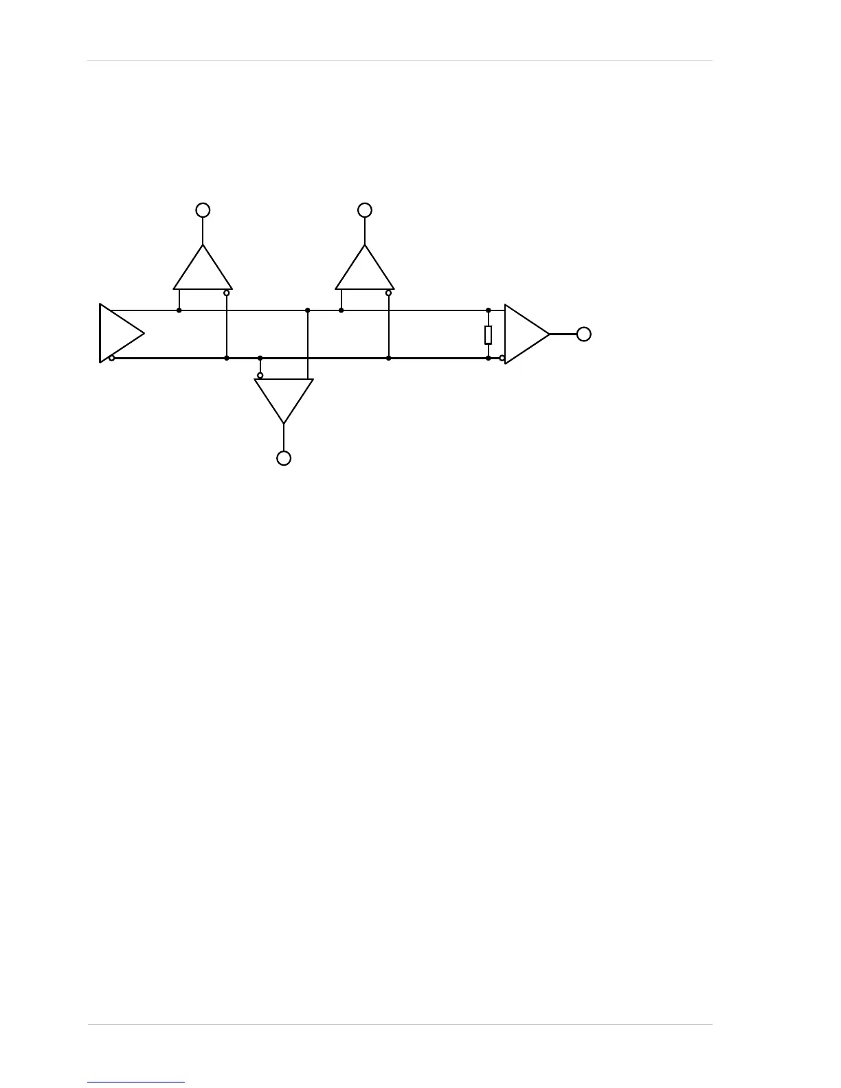
The RS-422 standard allows devices to be used with a bus structure to form an interface circuit. So,
for example, input line 1 on several different cameras can be connected via an RS-422 bus as
shown in Fig. 18.
Fig. 18: RS-422 Interface Circuit Including Four Receivers as an Example
Connected to the bus would be one camera as the "master" transmitter (driver D; only one driver
allowed) and up to ten cameras (receivers R), with the "master" transmitter sending signals to the
"slave" inputs of the receivers. The inputs of the receivers would be connected in parallel to the
driver via the bus.
The separations between receivers and bus should be as small as possible. The bus must be
terminated by a 120 ohm termination resistor (RT). Note that each RS-422 input on the cameras
includes a switchable 120 ohm termination resistor as shown in Fig. 17. When a camera input of
the last receiver in the bus terminates the bus (as shown in Fig. 18.: R4), the termination resistor
on that input should be enabled. You should not use multiple termination resistors on a single bus.
Using multiple termination resistors will lower signalling reliability and has the potential for causing
damage to the RS-422 devices.

 Loading...


