Installation
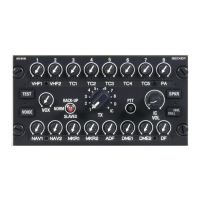
ACU6100 - CANbus and Device Address
36 ACU6100 DV64440.03 Issue 09 November 2019
The control panels (ACUs) are connected via two CANbus links (CAN1, CAN2).
When one CANbus fails, the devices automatically switch to the remaining connection.
Notice:
The ends of each bus must be terminated with 120 Ohm. It can be in the harness or on a own
connection block.
For correct operation when one ACU removed, a dummy mating connector must be connected in its
place.