Volume Adjustment
48 ACU6100 DV64440.03 Issue 09 November 2019
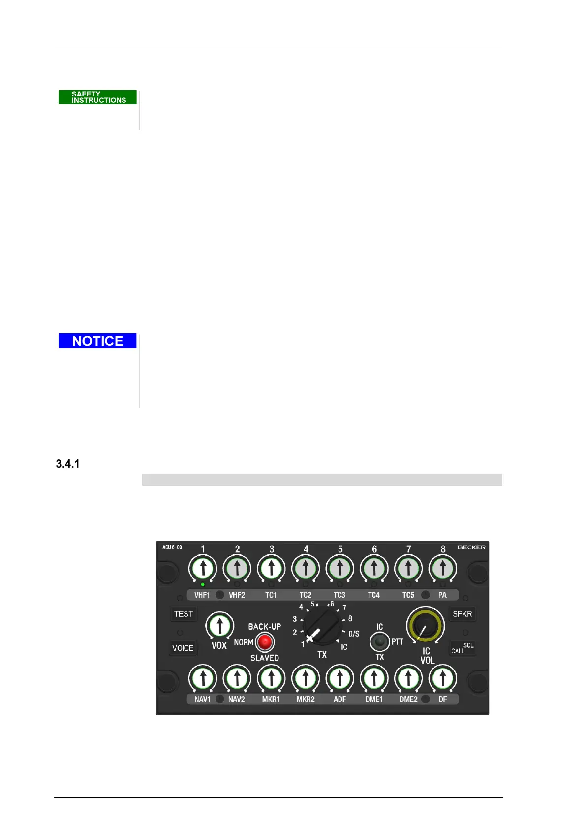
3.3 Start-Up
Excessive pulses on the DC bus of the aircraft may cause damage on electrical
circuits of any installed instrument.
Do not switch ON the device during engine start or shutdown
• The ACU6100 powers up with the main system power.
• The test routine will be started (test time ca. 4 s)
o The test status LED (yellow) is on.
o The internal circuits and the data transfer between ACU61 and REU6100 will be
examined.
• After successful test without failure the test status LED is off.
• If a failure was found the test status LED (yellow) flashes.
There are two procedure to continue, if a failure was found:
• (1) Push at the “TEST” button the failure will be ignored.
o If there is permanent problem inside the system, it will be found by the continuous
self-test routine and indicated again.
• (2) Set the "BACK-UP" switch to slaved or emergency mode (details see "Emergency
Operation" page 60).
• Some functions are only available when they are enabled for the user in
the configuration software*.
• The scope of functions is variant-dependent.
*For more information refer to the software manual "CSW6100... "(www.becker-
avionics.com/downloads/ → Intercom).
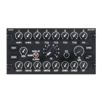
3.4 Volume Adjustment
Main Volume Adjustment
• The main volume is adjustable at any time.
• Turn the outer part of the double rotary knob (VOL) to adjust the volume.
o The main volume adjustment is for all audio channels which are on and
the fixed inputs 4...6.
Figure 16: Operation - Main Volume