Installation and Operation
DV64440.03 Issue 09 November 2019 ACU6100 35
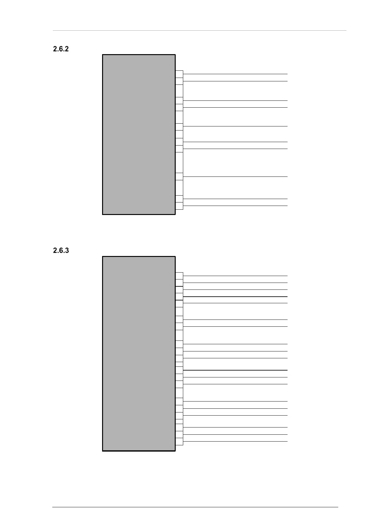
ACU6100 - Power Supply Connections
Figure 10: Wiring - Power Supply
ACU6100 - CANbus and Device Address
Figure 11: Wiring - Device Address, CANbus
C
D
G
F
H
B
K
J
E
A
P1
ACU61
Back-Up Switch out
Slaved Switch out
or Mask Mike Switch out
Dim Control1 in
Dim Control2 in
IC Hot Mike in
PTT in/out
DC2 +27.5 V
GND2
DC1 +27.5 V
GND1
L
M
A
B
N
U
V
C
D
P
P2
ACU61
Reset out
Resout in
CAN1 in (HI)
CAN1 in (LO)
CAN1 in (shield)
E
F
R
CAN1 out (HI)
CAN1 out (LO)
CAN1 out (shield)
G
H
S
CAN2 in (HI)
CAN2 in (LO)
CAN2 in (shield)
J
K
T
CAN2 out (HI)
CAN2 out (LO)
CAN2 out (shield)
Device Address Bit 0
Device Address Bit 1
Device Address Bit 2
Device Address Bit 3
Address Ground