FULL SIDE WASHER
1MANUL854 Belanger, Inc. * PO BOX 5470 * Northville, MI 48167 -5470 * Ph (248) 349-7010 * Fax (248) 380-9681 19
Installation
Utilities
Hydraulic
This section will explain the installation of the hydraulic connections.
The stainless-steel tubing atop the head frame assembly can be turned 180 degrees to
accommodate whichever side of the building your hydraulic unit is located on.
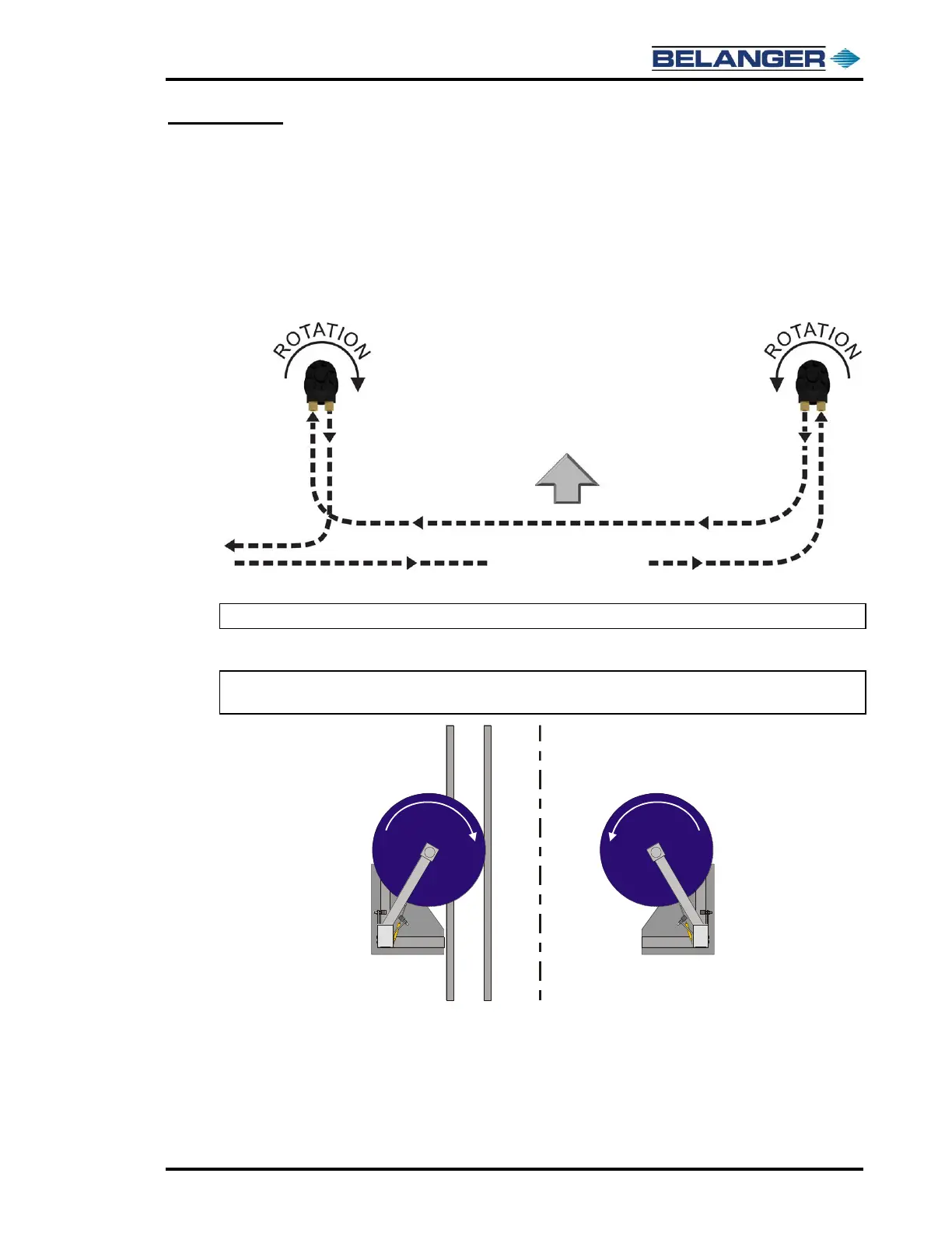
1) Connect the hoses to the motors per the diagram below.
Overhead view showing typical hydraulic routing to the motors.
Note: Above image shows a typical driver side hydraulic installation.
Confirming Wheel Rotation
Note: Be sure to match the wheel rotation shown below. If the rotation is opposite of what is
shown below, reverse the hydraulic feed lines to the motor.
 Loading...


