Take down the number of the pipe to be bent, find and
remove it from the deck. Remember to place a marker of
some type in its place. The cards are filed in numerical
sequence by the number shown on the top left section of
the card. Only the last four digits shown are in sequential
order. Some cards start with a prefix such as T3 or T5 then
are followed by a four digit number. ALWAYS disregard the
prefix and follow the last four digits only.
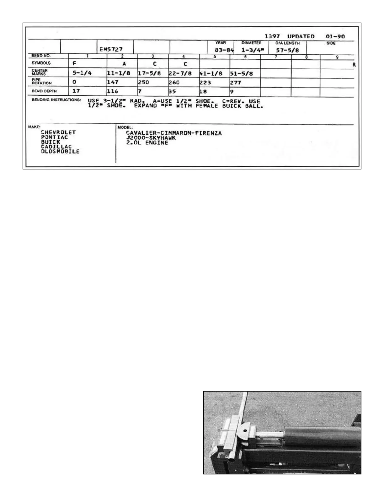
DEFINITION OF CARD
SECTIONS:
YEAR - Gives the year of the vehicle that the card pertains
to.
DIAMETER - The original equipment factory recommend-
ed tubing diameter for that particular vehicle,
O/A LENGTH - Overall length of tubing required for that
particular pipe. Also referred to as the cut-off point.
SIDE - When more than one section of tubing is required
for a particular card number, this section shows if it is the
front, rear, left or right side.
SYMBOLS - Shows certain symbols that pertain to indi-
vidual bending instructions that are explained in greater
detail in the BENDING INSTRUCTIONS section. The
symbol section also includes the descriptive “F” and “R”
symbols that indicate how the pipe fits on the vehicle. “F”
means front and “R” means rear.
CENTER MARKS - Refers to the actual locations or mea-
surements that the bends will be located.
PIPE ROTATION - Shows in degrees what the correct
pipe rotation (or plane) is for each bend.
BEND DEPTH - Shows in degrees what the correct bend
depth is for each bend.
MAKE - Gives the make of the vehicle. Chevrolet, Pontiac,
Ford, Chrysler, etc.MODEL - Gives descriptive factors
such as the model, engine and frame size.
BENDING INSTRUCTIONS - Shows what radius die will
be used in addition to other tooling such as half shoes
and three quarter shoes. Also gives instructions on
reversing and certain end-fInishing requirements. Not all
applications will be shown on the card.
Follow these step-by-step instructions to bend the pipe
for the card shown above.
1. Select the proper tubing size for the application as
called for in the DIAMETER SECTION of the card.
(See Recommended Tubing Chart on page 48) Wipe
tubing to remove excess oil.
2. Install the correct radius die as called for in the
BENDING INSTRUCTION section. Two back shoes
are required unless otherwise specifIed. Place tubing
in the bender between the back shoes and radius die
with the greater portion of the tubing extending out
the LEFT side of the bender. This is necessary so
that you can mark the tubing with the appropriate
CENTER MARKS shown on the card.
3. Engage the bending dies until the pusher
block springs are compressed and the tubing is held
fIrmly. Carefully control the advancement of the
radi us die so as not to dent or bend the tubing at this
time. (See figure 1-A)
16 Bender Operation Manual
Sample card layout to be used in conjunction with bending instructions.
Figure 1-A