If the return pressure needs adjusting, proceed as follows.
1. Turn the machine on.
2. Place a radius die and set of back shoes in
position. Tubing will not be required for this
operation.
3. Advance the radius die until it just comes in contact
with the back shoes.
4. Using the manual controls, initiate the retract
sequence and read the pressure shown on the
gauge located to the front of the machine.
5. If an adjustment is required, loosen the locking nut
that secures the adjusting screw.
6. To increase the pressure, turn the adjusting screw
slightly clockwise; to decrease, counter-clockwise.
Never exceed 350 P.S.I.
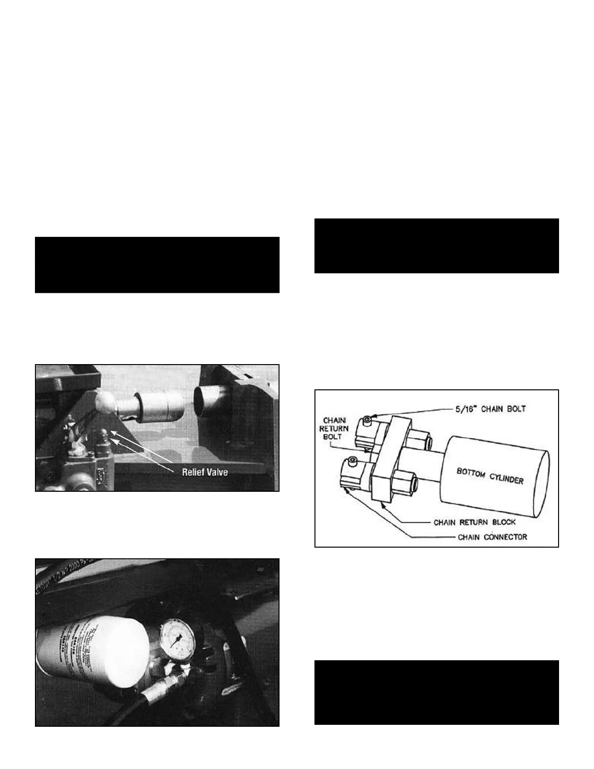
SYSTEM PRESSURE - Your bender has a built in relief
valve in order to control maximum pressure output for the
entire machine. As the fluid exits the hydraulic pump, it first
enters the swager control valve that contains an adjustable
“ball-check” relief valve. (See figure 3-A)
The normal operating system pressure should be set
at 3200 P.S.l. This pressure is read on the gauge located
near the center of the machine next to the hydraulic pump.
(See figure 3-B)
To check and adjust the system pressure, proceed as follows.
1. Turn the machine on.
2. Press the swager control valve down until the swager
cylinder is bottomed out.
3. When the cylinder bottoms out or is extended to
maximum travel the pressure will surge and the
machine will “groan” as the relief valve opens up and
fluid is redirected back to the reservoir. This is when
the reading should be taken.
4. If an adjustment is required, loosen the locking nut
that secures the adjusting screw on the relief valve.
5. To increase the pressure, turn the adjusting screw
slightly clockwise; to decrease, counter-clockwise.
Never exceed 3200 P.S.I.
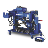
ADJUSTING THE CHAINS - When the chains are prop-
erly adjusted, the threaded chain connector will protrude
from the adjusting nut approximately one quarter of an
inch. Both chains should have equal tension. If one chain
has more slack than the other, tighten the chain connec-
tor adjusting nut using a 1-1/16” open end wrench.
NEVER tighten the chain connector so that it is bottomed
out against the chain return block. (See figure 3-C)
NOTE:
The chain return bolt has the tendency to loosen
during normal use. If it is necessary to tighten this bolt,
remove one of the chain connectors and tighten
using a 1-3/8” open end wrench.
After the bolt is secure, replace the chain
connector and adjust as described above.
34 Bender Operation Manual
CAUTION!
Never exceed 350 P.S.I. for the return pressure unless
specifically instructed to do so by the factory for
special circumstances.
CAUTION!
Never exceed 3200 P.S.I. for the system pressure
unless specifically instructed to do so by the factory
for special circumstances.
CAUTION!
If any part of the chain or assembly bolts appear to be
damaged in any way, discontinue use until
they are replaced.
Figure 3-A
Figure 3-B
Figure 3-C