43 Bender Operation Manual
The following section contains instructions and
illustrations to aid in electrical repair. Most electrical
components cannot be repaired and require only removal
and installation of new components. If replacement parts
are to be installed, refer to the wiring diagrams found on
pages 49 & 50.
CHECKING THE MICRO
SWITCHES / AUTOMATIC
MODELS
The micro switches shown below play a very important
part in the control features of your machine. These
switches remain in the circuit at all times in order for the
controls to function properly.
Each micro switch has three terminals for connecting the
necessary wires. These terminals will be labeled as
follows;
“C” or Common
“NO” or Normally Open
“NC” or Normally Closed
To tell if the micro switch is good, remove it from the
machine and use an ohmmeter to check the circuits as
follows;
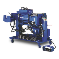
WITH THE SWITCH IN THE NEUTRAL POSITION -
Place one of the prongs from your ohmmeter on the “com-
mon” terminal of the switch and the other on the “normally
closed” terminal. At this time there should be continuity
between the two. There should be no continuity between
the “common” and “normally open” at this time.
(See Fig. 2-A)
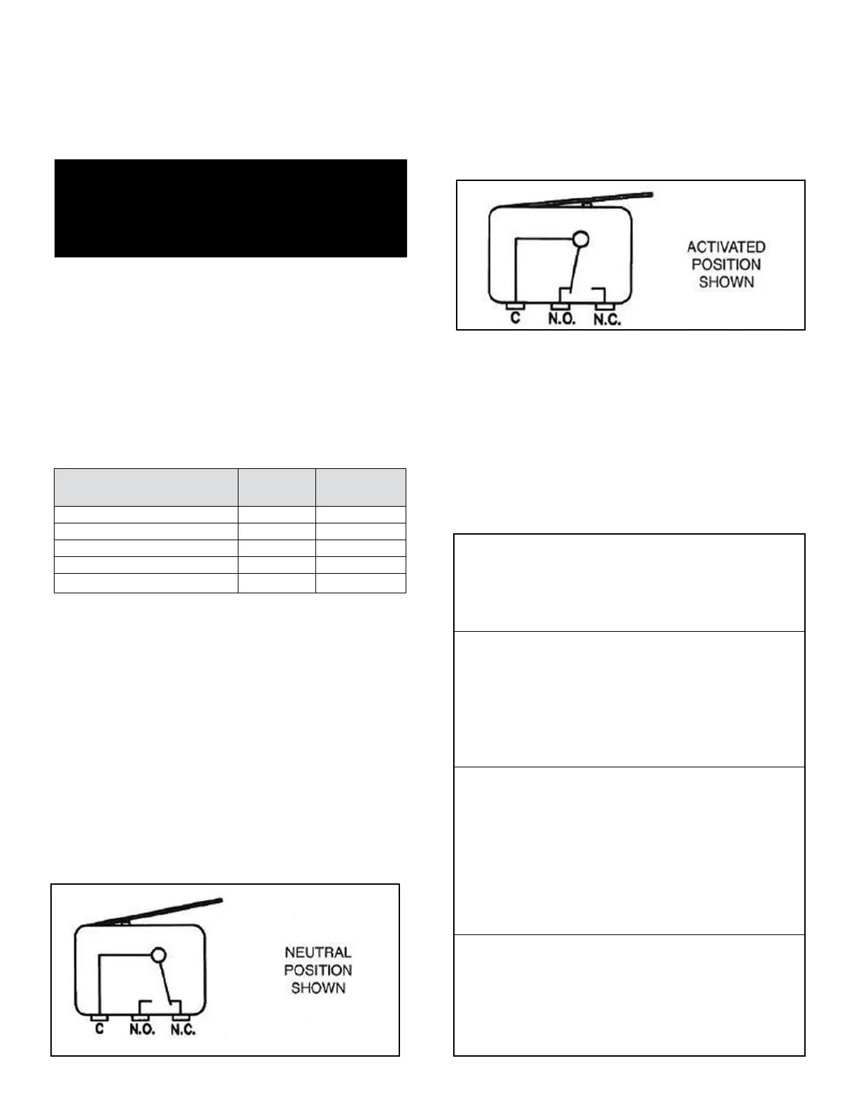
WITH THE LEVER OR BUTTON DEPRESSED - Place
one of the prongs from your ohmmeter on the “common”
terminal of the switch and the other on the “normally open”
terminal. At this time there should be continuity between
the two. There should be no continuity between the “com-
mon” and “normally closed” terminals at this time. (See
figure 1-A)
CAUTION:
Replace ALL faulty switches immediately.
NEVER attempt to bypass or “hot-wire” any of
the micro switches.
MOTOR CONNECTIONS
For motor lead connections, refer to the charts below. In
addition, to the motor lead wires it is necessary to connect
the green ground wire. Electric motor MUST be grounded
at all times.
Bender Operation Manual 43
DANGER!
This machine contains high voltage. Disconnect power
at the receptacle before performing any electrical
repairs. Secure plug so that it cannot be accidentally
plugged in during servicing.
Figure 2-A
Figure 1-A
220 Volt 60HZ Single Phase
Incoming Power Motor Leads
Line 1 5 and 1
Line 2 8 and 4
To reverse rotation, interchange lines 5 and 8
220 Volt 60HZ Three Phase
Incoming Power Motor Leads
Line 1 3 and 9
Line 2 2 and 8
Line 3 1 and 7
Twist together 4, 5, 6
To reverse rotation, interchange any two line leads
440 Volt 6OHZ Three Phase
Incoming Power Motor Leads
Line 1 1
Line 2 2
Line 3 3
Twist together 6 and 9
Twist together 5 and 8
Twist together 4 and 7
To reverse rotation, interchange any two line leads
220 Volt 50HZ Three Phase
Incoming Power Motor Leads
Line 1 1, 6, 7, 12
Line 2 2, 4, 8, 10
Line 3 3, 5, 9, 11
To reverse rotation, interchange any two line leads
MICROSWITCH
DESCRIPTION
“BA”
MODELS
"BAS"
MODELS
Top Micro Switch X X
Right Foot Switch X X
Left Foot Switch X X
Depth -of-Bend Switch X
Zero AngIe Micro Switch X