INTRODUCTION
Your new bender is a “press-style” bender that is capable
of bending, flaring and swaging tubing up to 3 inches in
diameter. The thickness of the tubing plays an important
part. (See previous chart for recommended tubing
allowances.) The front of the bender is where all the bend-
ing is performed. The top cylinder activates the bending or
radius die which moves forward through the back shoes.
The bottom cylinder keeps pressure applied to the back
shoes by a chain assembly and integrated hydraulic
sequence valve. In addition to the contoured shape of the
radius dies, resistance pressure is applied to help the tub-
ing maintain it's shape.
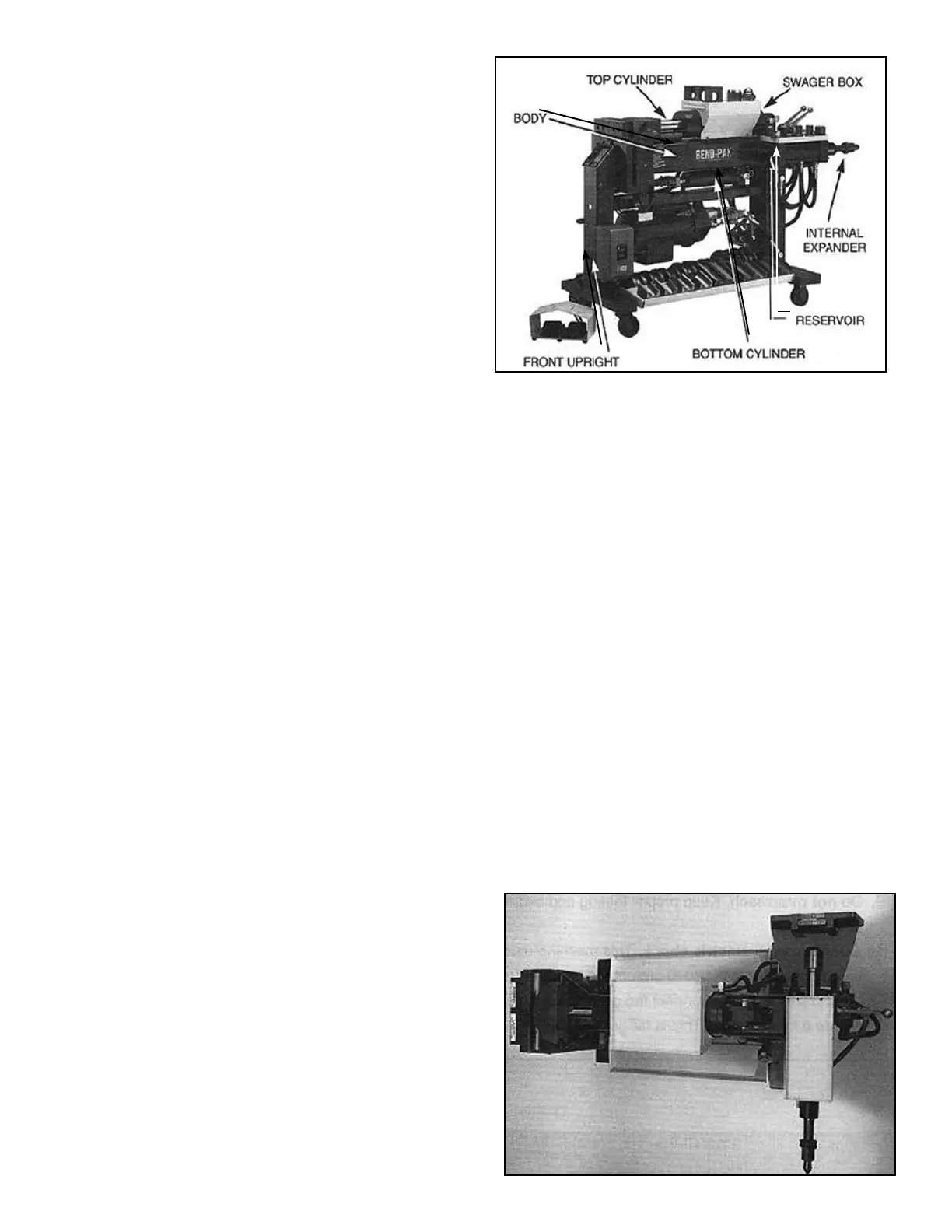
DEFINITION OF TERMS
The following definitions explain the major components
and operating features of your machine. The RIGHT,
LEFT, and REAR sides of the bender are relative to the
FRONT of the machine where all bending is performed.
BENDER- The whole machine including all end
finishing components.
BODY- The main 6” x 6” tubular structure that sits
horizontal to the floor and is located just below the top
cylinder.
SWAGER OR SWAGER BOX- The expanding/flaring
unit located to the rear of the bender which utilizes
pipe collars in conjunction with bullet shaped expander/
forming dies to perform a variety of tube end finishing.
INTERNAL EXPANDER- The expanding/flaring unit
located to the rear of the machine that utilizes seg-
mented expander dies. These “segment sets” are expand-
ed by the means of a tapered arbor pulled through their
center. This style of end finishing is usually required with
shorter pieces of tubing such as muffler nipples which do
not allow the use of a collar.
TOP CYLINDER- The main hydraulic bending cylinder
located at the top of the bender. It's primary function is to
activate movement of the radius dies.
BOTTOM CYLINDER- The hydraulic cylinder located
just below the body of the bender. It's primary function is
to apply resistance pressure to the back shoes as the
radius die pushes through.
RESERVOIR-The rear vertical leg that contains the
hydraulic oil.
FRONT UPRIGHT- The front vertical leg.
BENDER MODELS
There are nine different bender models available.
1000-BL 1000-BAS 1000-BA
1302-BL (Blue-Bullet) 1302-BAS 1302-BA
1502-BL 1502-BAS 1502-BA
The following is a brief description of their controls and
operating features. The model nomenclature consists of a
number (1302) followed by letters BA. The numbers des-
ignate what style frame assembly is used while the letters
signify the control features.
FRAME CONFIGURATION
1000 Series- A machine capable of bending only. Does
not come with any end finishing capabilities.
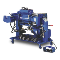
1302 Series- A machine capable of bending and end
finishing. Equipped with both swager and internal
expander. A double-ended hydraulic cylinder is used for
both end finishing functions. The end finishing assembly,
(the swager and internal expander) is positioned
“cross-wised” on the rear of the machine.
6 Bender Operation Manual
Overhead view of Model 1302
Side view of Bender showing major components.