6. It will not be necessary to loosen the rear most bolt `
on the guide plate for this service.
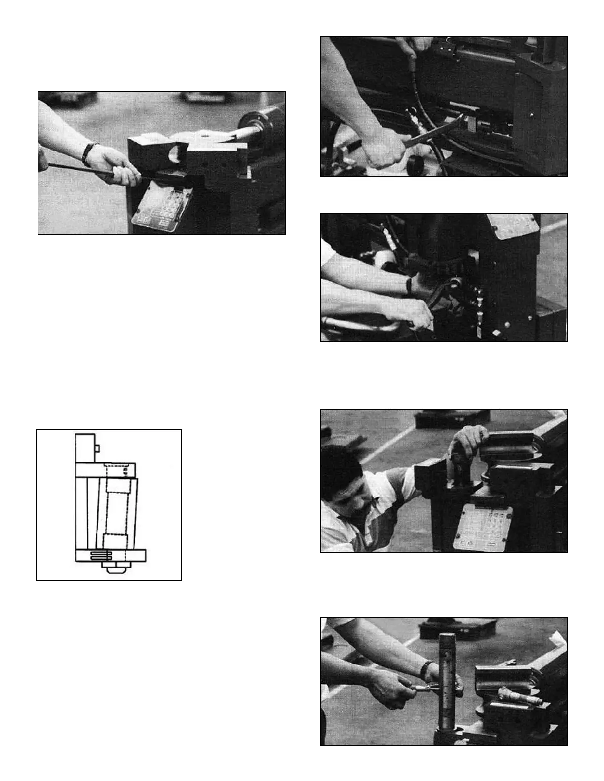
7. Using a pry bar, elevate the front of the guide plate.
(See figure 2-A)
8. Using shim stock .002 - .005 thick, shim underneath
the guide plate as required until proper levelness is
achieved.
9. Tighten all allen bolts on the guide plate then grease
well.
VISUALLY CHECKING THE
BARREL BUSHlNGS FOR WEAR
The barrel bushings should be checked every six months
for excessive wear. If the barrel bushings become worn,
the barrel shafts will have too much play and the gates
will become misaligned causing the tubing to wrinkle.
(See figure 2-B)
To check the barrel bushings for excessive wear it is nec-
essary to completely remove one of the gate assemblies
and visually check the bronze bushings. The left gate
assembly is the easiest to remove. If the bushings are
worn on the left side of the barrel, then the right side
bushings will be equally worn. There are two 2-1/2” x 2” x
1-1/2” bronze bushings press fitted on the top and bottom
of each side of the barrel assembly. To visually check
these bushings, follow the steps outlined below.
1. Disassemble the left side chain assembly by removing
the left side chain connector. (See figure 2-C)
2. Remove the barrel shaft nut located below the left
side gate assembly. (See figure 3-A)
3. Using a rubber mallet, carefully tap the shaft up and
out of the barrel. BE CAREFUL when removing shaft
to prevent threads from being damaged. Be sure to
keep shaft key as it is required for re-installation.
(See figure 3-B)
4. Remove the left gate assembly.
5. Clean shaft and inside of barrel of all grease and debris.
6. Visually check shaft for excessive wear. Replace
shaft if diameter is less than 1.997”. (See figure 3-C)
36 Bender Operation Manual
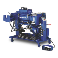
This diagram shows
the gate assembly
misaligned with the
barrel due to
excessive
wear on the barrel
bushings.
Figure 2-C
Figure 3-A
Figure 3-B
Figure 2-B
Figure 3-C
Figure 2-A