7 Bender Operation Manual
Bender Operation Manual 7
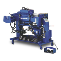
1502 Series- A machine capable of bending and end fin-
ishing. Equipped with both swager and internal expander.
Individual hydraulic cylinders are utilized for both end fin-
ishing functions. The swager and internal expander are
positioned at the rear of the machine, one on each side
and are positioned parallel with the main body.
CONTROL FEATURES
BL or BLUE-BULLET Models- A hydraulic control valve
is located at the front of the machine at knee height that
allows the operators to manually control the machine with
their leg. A degree plate is mounted up front that shows
proper bend depths. This model does not
incorporate any automatic bending features.
BAS Models- These models have two different control
modes. An electric foot switch assembly for manual bend-
ing operations and a three-button control board for auto-
matic functions. The degrees of bends are shown on a
degree plate mounted near the front of the machine which
also incorporates an adjustable slide pointer that can be
set to any desired bend depth. The control board consists
of three colored buttons; GREEN, BLUE and RED; each
with its own operating functions. If you choose to use the
machine in the automatic mode, you would simply set the
pointer to 90 degrees for example, then press the GREEN
button. At this time the bending head would activate and
the radius die would begin to move forward. After the
desired bend depth has been reached, the machine would
automatically initiate the retract sequence that returns the
die to the original
starting position. The BLUE button is for automatically
returning the die to the original starting position while the
RED button is an emergency stop control. The electric foot
switches will override the three button controls.
BA Models - These models have two different control
modes; an electric foot switch assembly for manual bend-
ing operations and a digital control board for automatic
functions. The digital control board eliminates the depth of
bend scale and replaces it with a digital readout labeled
“DIE ANGLE”. It also offers the user the capability to “pro-
gram” certain bend depths in a desired sequence. When
the power is turned off, all memory is erased. Once a bend
depth is programmed into memory the number appears in
a L.E.D. window labeled “SET ANGLE.” The bend
sequence is initiated by pressing the “AUTO” button. At
this time the die moves forward and upon reaching the
desired bend depth immediately retracts to the original
starting position. An emergency “STOP” button pauses
the machine at any time, and an additional auto “REVERSE”
button activates the return sequence. The electric foot
switches will override the digital controls.
INSTALLING THE
ELECTRICAL PLUG
Before installing a plug on the end of the power cord it is
important to check for proper voltage, phase, and amp
requirements. The tag attached to the end of the power
cord, or the motor identification plate will show this
necessary information. Due to the high amps and voltage
required to operate this machine at long durations, it is
recommended that you DO NOT USE AN EXTENSION
CORD LONGER THAN 15 FEET. This motor must be
grounded. The GREEN wire is for ground only. All wiring
should be done by a certified electrician only. Damage
to the motor caused by improper wiring is not covered
under warranty.
Overhead view of Model 1502
Three button control
Digital
control
board
D.O.B. Plate