4. Leave at least three inches of tubing extended
beyond the inside edge of the adapter collar.
(See figure 1-A)
5. Snug the collar back into the clamp blocks by gently
pushing back on the collar assembly.
6. Slowly, while depressing the valve handle down,
move the shaft forward until the tool enters the tubing.
Be sure that the tool is centered with the tubing.
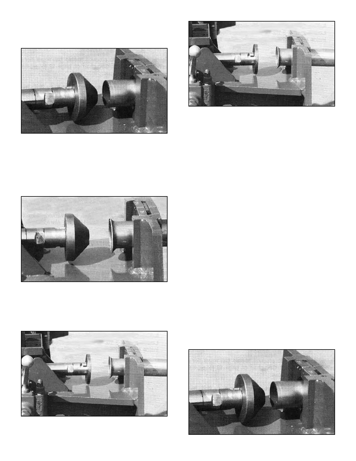
7. Slowly, move the tool forward until the desired flare
is achieved. (See figure 2-A)
8. Retract the die by lifting up on the control handle.
You have now completed the 45 degree flare.
9. To complete the FLAT FLARE proceed as follows.
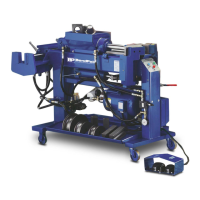
10. After retracting the cylinder, install the flattening tool
as shown below.
11. Slowly, move the tool forward until the flare forms a
flat surface. (See figure 2-B)
12. Retract the die by lifting up on the control handle.
13. Separate the collar from the tubing. Remove tooling
and return to the storage area.
USING THE HPF-300 TO MAKE A MANIFOLD FLANGE
IMPORTANT NOTE:
When making a manifold flange it is necessary to
first install the pipe flange or clamp around the
tube prior to finishing the ends.
On this application it is necessary to use a scrap piece of
tubing approximately 1-1/2” long of the same O.D. size.
This tubing section will be inserted into the tubing end to
form a gasket retainer.
Follow these steps to produce a manifold flange using
the HPF-300 tool. See chart on page 12 for typical end
finishing illustrations.
1. Retract the swager cylinder completely by lifting the
valve handle up.
2. Install the HPF-300 tool on the ST-1 adapter attached
to the end of the cylinder shaft.
3. Install the required HAC adapter collar around the
tubing and position within the swager clamp blocks.
4. Leave at least three inches of tubing extended
beyond the inside edge of the adapter collar.
(See figure 2-C)
28 Bender Operation Manual
Figure 2-B
Figure 2-A
Figure 2-C
Figure 1-A