29 Bender Operation Manual
Bender Operation Manual 29
5. Snug the collar back into the clamp blocks by gently
pushing back on the collar assembly.
6. Slowly, while depressing the valve handle down,
move the shaft forward until the tool enters the tubing.
Be sure that the tool is centered with the tubing.
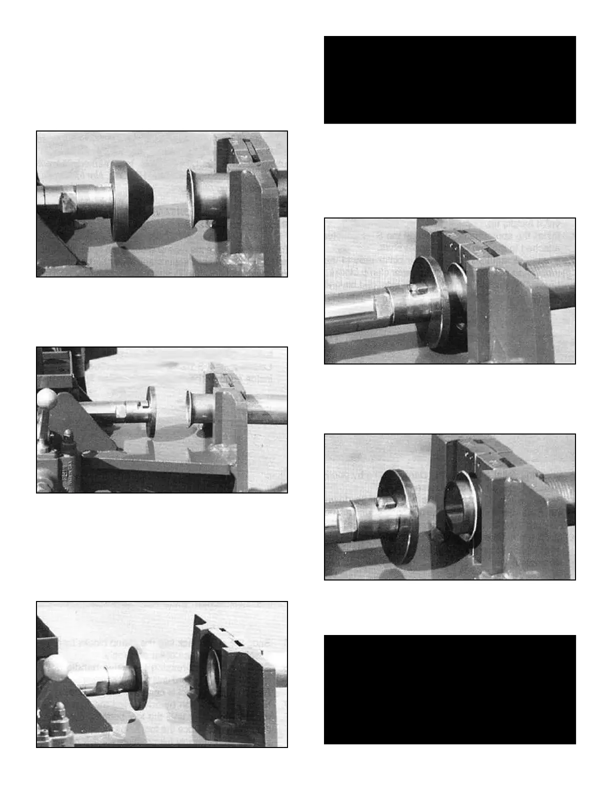
7. Slowly, move the tool forward until a 45 degree flare
is achieved. (See figure 3-A)
8. Retract the die by lifting up on the control handle. You
have now completed the 45 degree flare.
9. After retracting the cylinder shaft, install the flattening
tool as shown below.
10. Now, pull the flared tubing end up against the
chamfered edge of the adapter collar as shown below.
THIS STEP IS VERY IMPORTANT so that the tubing
end is retained within the clamped area. This will prevent
the flared end from swelling when the insert is pressed
in.
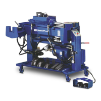
11. Insert the scrap pipe nipple into the flared end of the
tubing. The nipple should hold itself in position.
12. Remove hands from the swaging area and slowly
move the tool forward until the scrap nipple is forced
into the tube opening. Stop when the scrap nipple
protrudes 1/2” from the tube end. (See figure 3-B)
13. Retract the die by lifting up on the control handle.
14. This will form a seat for the round donut gasket as
shown below.
15. Separate the collar from the tubing. Remove tooling
and return to the storage area.
CAUTION!
Pay careful attention when performing the following
steps. KEEP HANDS CLEAR from all pinch points.
ALWAYS remove hands from the expanding area
when cylinder is in motion.
ALWAYS wear protective safety goggles.
CAUTION!
Remember, on 1302 models the swager side of the cyl-
inder moves simultaneously when operating the inter-
nal expander. ALWAYS REMOVE TOOLING FROM
THE SWAGER AREA when finished to avoid damage
to the tooling and cylinder when the internal expander
is being used.
Figure 3-B
Figure 3-A