5. Loosen the set screw on the adjustable trip arm
located directly underneath the depth-of bend plate
and adjust so that it just activates the micro switch.
6. Re-tighten the set screw.
7. Retract the radius die and re-check.
8. If further adjustment is required, repeat steps.
CALIBRATING THE DIGITAL
READOUT DISPLAY /
“BA”MODELS
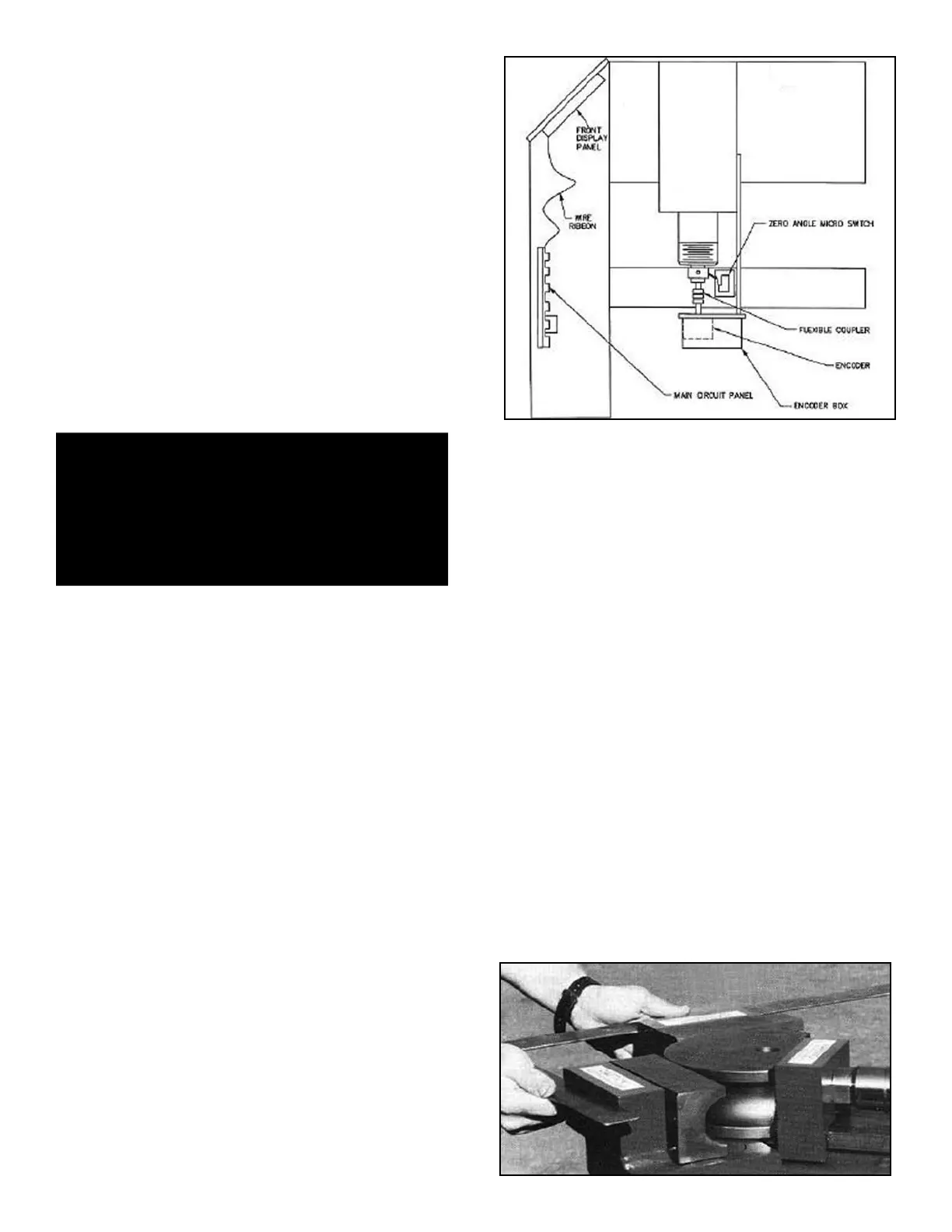
Automatic depth-of-bend and digital readout functions on
all “BA” models are performed by an electronics package
consisting of three main components. The circuit board
assembly, digital encoder and the zero angle micro
switch. (See figure 3-C)
t Circuit board assembly - The printed circuit board
is made up of three basic components. The main circuit
panel, front display panel and wire ribbon that connects
the two. The main circuit panel is held in position by
“card guides” and then plugged into a “pin-edge” connec-
tor mounted internally in the front upright of the bender. A
bypass board for trouble shooting is also attached
(stored) “piggyback” style on the back of the main circuit
panel. (See page 41 for proper use of jumper board.)
t Digital encoder - The digital encoder is located just
below the right side gate assembly and enclosed in a
metal box. As the encoder rotates by the means of a
flexible coupler attached to the barrel shaft, it registers
degrees and shares this information with the main circuit
panel.
t Zero angle micro switch - The zero angle micro
switch is located up front just below the right side gate
assembly and attached to the bender frame. The zero
angle micro switch has three distinct functions.
1. lnitiates the counting cycle and serves as an adjust-
ment device for properly calibrating the die angle.
2. Resets the die angle to zero upon retraction of the
radius die.
3. Advances the “steps” in the STATION window when
using the MEMORY function.
NOTE:
Only slight adjustments of 4 degrees or less can be
made to the die angle reading on digital models. The
digital readout is accurately maintained with the help
of logic functions in the digital control
board and optical sensors of the encoder. The
system automatically re-calibrates itself upon full
retraction of the radius die as the zero angle micro
switch is tripped. By adjusting the trip arm that
activates the zero angle micro switch you can
effectively “stall” or advance the counting process
which will in turn change the die angle reading. If
the die angle appears to be more than 5 degrees
out of calibration it is most likely a faulty encoder.
Dirt, oil or moisture will contaminate the encoder
and cause it to malfunction. If the encoder
becomes contaminated, remove from the machine
and clean with alcohol or T.V. tuner spray.
DO NOT use harsh or oil based solvents.
To properly calibrate the digital readout, follow the steps
outlined below.
1. Turn the machine on.
2. Place a set of bending dies in position.
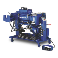
3. Using a carpenters square, advance the radius die
until the back gates are at a true 90 degrees, con-
tacting the inside of the square evenly across the
front. (See figure 1-A)
40 Bender Operation Manual
DANGER!
This machine contains high voltage. Disconnect power
at the receptacle before performing any electrical
repairs. Secure plug so that it cannot be accidentally
plugged in during service.
Figure 1-A
Figure 13-C