41 Bender Operation Manual
4. Read the degree of bend shown in the DIE ANGLE
window on the control board and make the following
adjustments.
NOTE:
Before making any adjustments, check to make sure that
the flexible coupler or “U-Joint” is functioning properly.
Excessive free-play will cause irregular encoder read-
ings. If there is excessive play between the steel roller
plates and the nylon rider, loosen the set screws and
snug up the coupler assembly. Be careful not to exert
excessive pressure on the encoder shaft.
The DIE ANGLE display shows a few degrees LESS
than 90° - This means the gates are moving slightly
before the micro switch deactivates and starts the count-
ing process. To make the proper adjustment, loosen the
trip arm set screw and adjust it slightly AWAY from the
micro switch lever so that upon initial movement of the
gate assembly the switch immediately deactivates.
ALWAYS BE SURE that when the gates return to zero, the
trip arm still contacts the micro switch lever enough to
activate it
The DIE ANGLE display shows a few degrees MORE
than 90° - In most cases this signifies that the encoder is
malfunctioning. Return the radius die back to zero then
slowly advance the radius die and check the DIE ANGLE
display for irregularities. If the counting appears to be in
proper sequence, then loosen the set screw on the trip arm
and adjust it slightly TOWARDS the zero angle micro switch
lever. DO NOT adjust the trip arm far enough to allow it to
“crash” into the micro switch upon full gate closure.
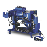
NOTE:
The back gates on digital models should close at a slight
negative angle. This is to compensate for the initial 1/8”
of forward travel (or movement) the gate needs to allow
the trip arm to deactivate the zero angle micro switch
and start the counting process. (See figure 1-B)
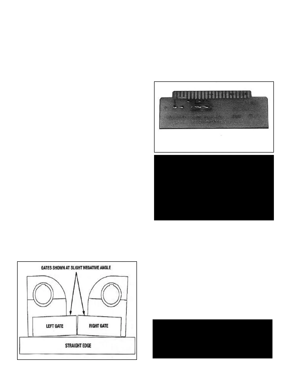
USING THE JUMPER BOARD
All “BA” models have a bypass device or “jumper board”
included that can be used to effectively bypass the digital
control board for trouble shooting or diagnostic purposes.
ALWAYS consult the factory before attempting to use the
jumper board. The jumper board is stored within the front
upright of the bender and attached to the back side of the
main circuit panel by retaining clips.
(See figure 1-B)
To remove and install the jumper board, follow the steps
outlined below.
1. With the machine unplugged, remove the four allen
screws that secure the front display panel.
2. Reach in and carefully pull up on the main circuit
panel using the white handle, until it disconnects
from the connector located within the front upright.
3. Remove the jumper board from the back side of the
main circuit panel and check the fuse.
4. Install the jumper board narrow end down with THE
FUSE TO THE REAR by gently sliding it down
between the card guides until it plugs into the
connector. The jumper board MUST be plugged firmly
into the connector to function properly.
Bender Operation Manual 41
Figure 1-B
WARNING!
The jumper board should be used for temporary
diagnostic purposes only and was not designed to
permanently bypass the main circuit panel. USE OF
THE JUMPER BOARD alters the foot switch controls to
high voltage. NEVER operate the machine in or around
water or damp environments. This machine contains
high voltage. Disconnect power at the receptacle before
performing any electrical repairs. Secure plug so that it
cannot be accidentally plugged in during service.
WARNING!
If the machine continues to malfunction with the
jumper board in place, discontinue use immediately
and consult factory.