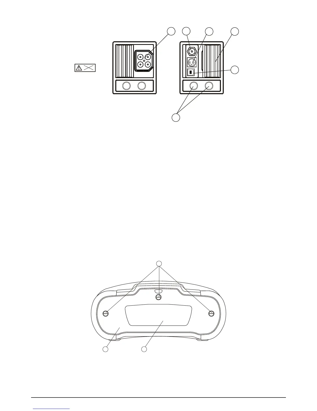
Fig. 3.2: Connector panel
Legend:
1 Test connector
Warning:
Maximal allowed voltage between test terminals and earth is 600 V. Maximal allowed voltage
between test terminals is 550 V.
2 Power supply socket
3 Protection connector cover (prevents the simultaneous connection of test cable and charger)
BENNING IT 120 B only: In resistance to earth function test, the connector terminals are used
as follows:
- L/L1 black test lead is used for the auxiliary earth electrode (H).
- N/L2 blue test lead is used for the earth electrode (E).
- PE/L3 green test lead is used for the probe (S).
4 RS 232 connector (BENNING IT 120 B only)
5 USB connector (BENNING IT 120 B only)
6 Current clamp input
3.3 Back panel