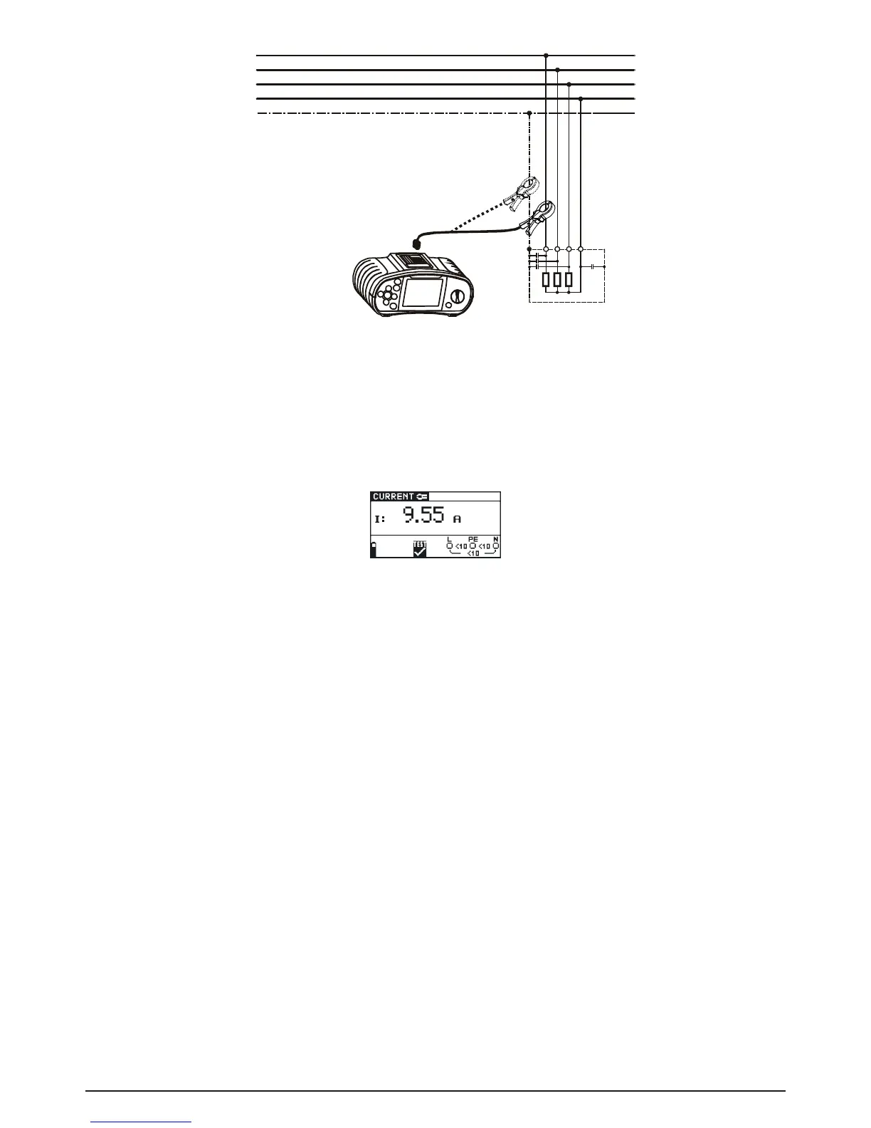
Fig. 5.48: Current clamp connection
Step 3 Check the displayed warnings and online voltage/terminal monitor before starting the
measurement. If OK, press the TEST key to start the measurement. The measuring re-
sult is shown on the display during measurement.
To stop measurement at any time press the TEST key again. The last measured result is
displayed.
Fig. 5.49: Example of TRUE RMS current measurement result
Displayed results:
I TRUE RMS current
Save displayed results for documentation purposes. Refer to chapter 6.1 for further information on
setting functions and saving of measurement results.
Note:
- Only current clamps with a transformation ratio of 1000:1 should be connected. We recom-
mend to use the current clamp adapter BENNING CC 2 which can take measurements from
0.5 A - 20 A.
- An additional error of the connected current clamp has to be included into the measuring error!
Warning:
- Do not apply voltage to this terminal. The maximum permissible continuous current of this ter-
minal is 20 mA
^
=
20 A measuring current!
5.11 Illumination measurement (LUX) (BENNING IT 120 B only)
The illumination measurement can be performed with the appropriate luxmeter probes (BENNING
Luxmeter type B). The probe is connected to the RS232 port.
How to perform illumination measurement:
Step 1 Select LUXSENSOR with the function selector switch, the following menu is displayed: