32
5.3.7 Trip-out time (RCDt)
Trip-out time measurement is used to verify the effectiveness of the RCD. This is achieved by a
test simulating an appropriate fault condition. Trip-out times vary between standards and are listed
below.
Trip-out times according to EN 61008 / EN 61009:
½×I
∆N
*)
I
∆N
2×I
∆N
5×I
∆N
General (non-
delayed) RCDs
t
∆
< 300 ms t
∆
< 300 ms t
∆
< 150 ms t
∆
< 40 ms
Selective (time-
delayed) RCDs
t
∆
< 500 ms
130 ms < t
∆
<
500 ms
60 ms < t
∆
<
200 ms
50 ms < t
∆
<
150 ms
Trip-out times according to IEC 60364-4-41:
½×I
∆N
*)
I
∆N
2×I
∆N
5×I
∆N
General (non-
delayed) RCDs
t
∆
< 999 ms t
∆
< 999 ms t
∆
< 150 ms t
∆
< 40 ms
Selective (time-
delayed) RCDs
t
∆
< 999 ms
130 ms < t
∆
<
999 ms
60 ms < t
∆
<
200 ms
50 ms < t
∆
<
150 ms
Trip-out times according to BS 7671:
½×I
∆N
*)
I
∆N
2×I
∆N
5×I
∆N
General (non-
delayed) RCDs
t
∆
< 1999 ms t
∆
< 300 ms t
∆
< 150 ms t
∆
< 40 ms
Selective (time-
delayed) RCDs
t
∆
< 1999 ms
130 ms < t
∆
< 500
ms
60 ms < t
∆
<
200 ms
50 ms < t
∆
<
150 ms
*) Test current of ½×I
∆N
cannot cause trip-out of the RCDs.
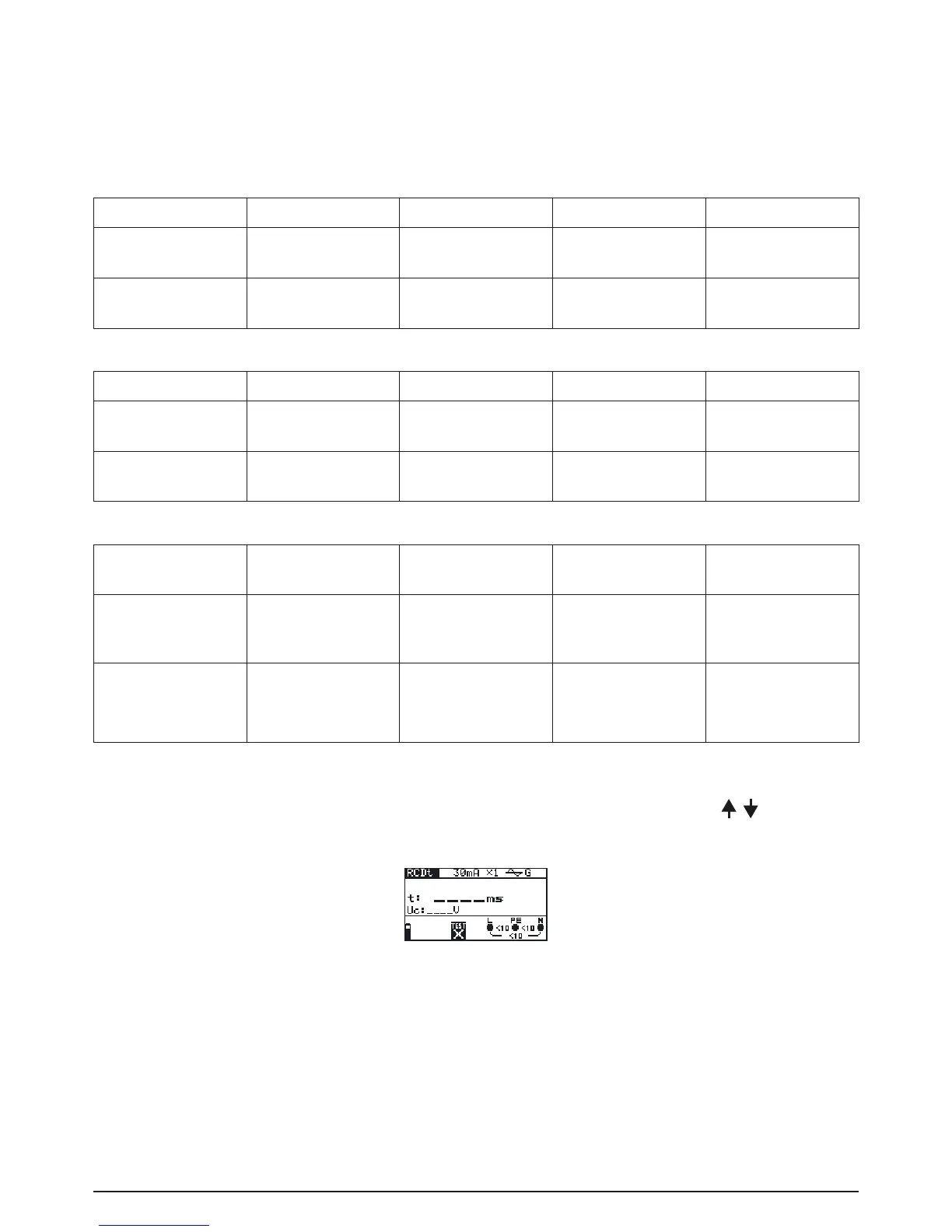
How to perform trip-out time measurement:
Step 1 Select FI/ RCD TEST (RCD) with the function selector switch. Use the
/ . keys to se-
lect RCDt (trip-out time of the RCD). The following menu is displayed:
Fig. 5.17: Trip-out time measurement menu
Connect the test cable to the BENNING IT 110/ BENNING IT 120 B.
Step 2 Set the following measuring parameters:
- Nominal differential trip-out current
- Nominal differential trip-out current multiplier
- RCD type, and
- Test current starting polarity