37
Save displayed results for documentation purposes. Refer to chapter 6.1 for further information on
setting functions and saving of measurement results (BENNING IT 120 only).
Note:
- The measurement of contact voltage in pre-test does not normally trip an RCD. However, the
triplimitmaybeexceededasaresultofleakagecurrentowingtothePEprotectiveconductor
or via a capacitive connection between L and PE conductors.
- The autotest sequence stops when the trip-out time is outside the allowed time period.
- Whensettingthefollowingparameters,theautomatictestingsequencewillbenishedalready
after having measured the time t4:
FI/RCD of type A, nominal fault current I
∆N
: 300 mA, 500 mA, 1000 mA
FI/RCD of type B, nominal fault current I
∆N
: 300 mA, 500 mA
- Whensettingthefollowingparameters,theautomatictestingsequencewillbenishedalready
after having measured the time t2:
FI/RCD of type B, nominal fault current I
∆N
: 1000 mA
5.4 Loop impedance and prospective short-circuit current (Zs/ Ik)
Two loop impedance measuring sub-functions are available:
- The Zl sub-function performs measurements in supply systems without RCDs.
- The Zs
rcd sub-function performs measurements in supply systems with RCDs installed (with
nominal differential trip-out current 10 mA)
5.4.1 Loop impedance (loop resistance, Zl)
The loop impedance is a complex AC impedance within the fault loop when a short-circuit to ex-
posed conductive parts occurs (conductive connection between phase conductor and protective
earth conductor). For measuring the loop impedance (loop resistance), the BENNING IT 110/
BENNING IT 120 B uses a 2.5 A test current.
The prospective short-circuit current (fault current) is calculated on the basis of the measured loop
impedance (loop resistance) as follows:
where
U
n
Voltage range
115 V 100 V ≤ U
L-PE
< 160 V
230 V 160 V ≤ U
L-PE
≤ 264 V
Becauseofdifferentdenitionsoftheprospectiveshort-circuitcurrent(faultcurrent)I
PFC
in diffe-
rent countries, the user can set the scaling factor in the Setup menu (see chapter 4.4.2).
PFC=Prospective Fault Current
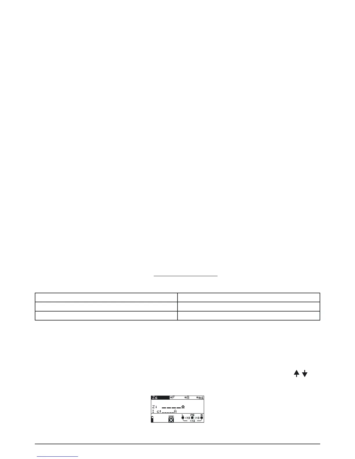
How to perform the loop impedance measurement:
Step 1 Select Zs/Ik (L-PE) (loop impedance) with the function selector switch. Use the /
keys to select the Zl sub-function. The following menu is displayed:
Fig. 5.28: Loop impedance measurement menu