36
After re-switching the RCD the autotest sequence automatically proceeds with step 4.
4. Trip-out time measurement with the following measurement parameters:
- Test current I
∆N
- Test current started with the negative half-wave at 180°
Measurement normally trips an RCD within allowed time period. The following menu is displayed:
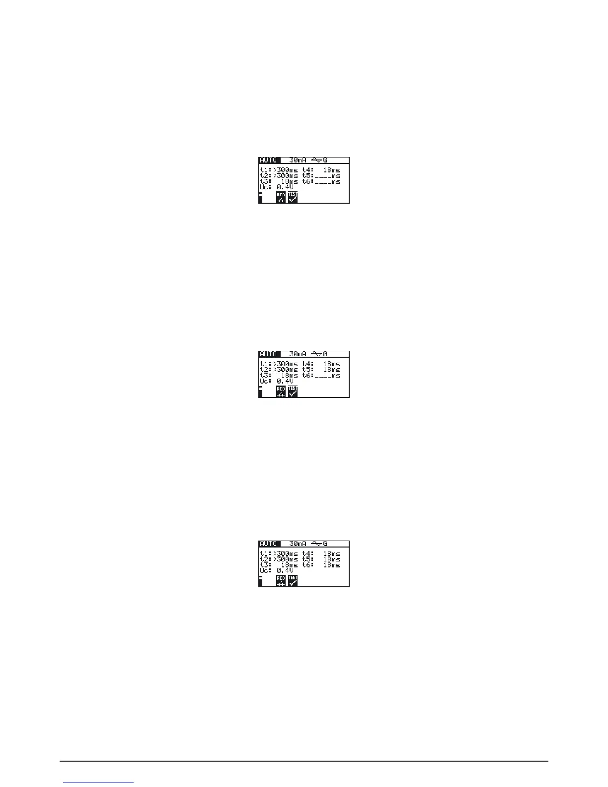
Fig. 5.25: Step 4 RCD autotest results
After re-switching the RCD the autotest sequence automatically proceeds with step 5.
5. Trip-out time measurement with the following measurement parameters:
- Test current 5×I
∆N
- Test current started with the positive half-wave at 0°
Measurement normally trips an RCD within allowed time period. The following menu is displayed:
Fig. 5.26: Step 5 RCD autotest results
After re-switching the RCD, the autotest sequence automatically proceeds with step 6.
6. Trip-out time measurement with the following measurement parameters:
- Test current 5×I
∆N
- Test current started with the negative half-wave at 180°
Measurement normally trips an RCD within allowed time period. The following menu is displayed:
Fig. 5.27: Step 6 RCD autotest results
Displayed results:
t1: Step 1 trip-out time result (½×I
∆N
, 0
°
)
t2: Step 2 trip-out time result (½×I
∆N
, 180°)
t3: Step 3 trip-out time result (I
∆N
, 0
°
)
t4: Step 4 trip-out time result (I
∆N
, 180
°
)
t5: Step 5 trip-out time result (5×I
∆N
, 0
°
)
t6: Step 6 trip-out time result (5×I
∆N
, 180
°
)
Uc: Contact voltage