27
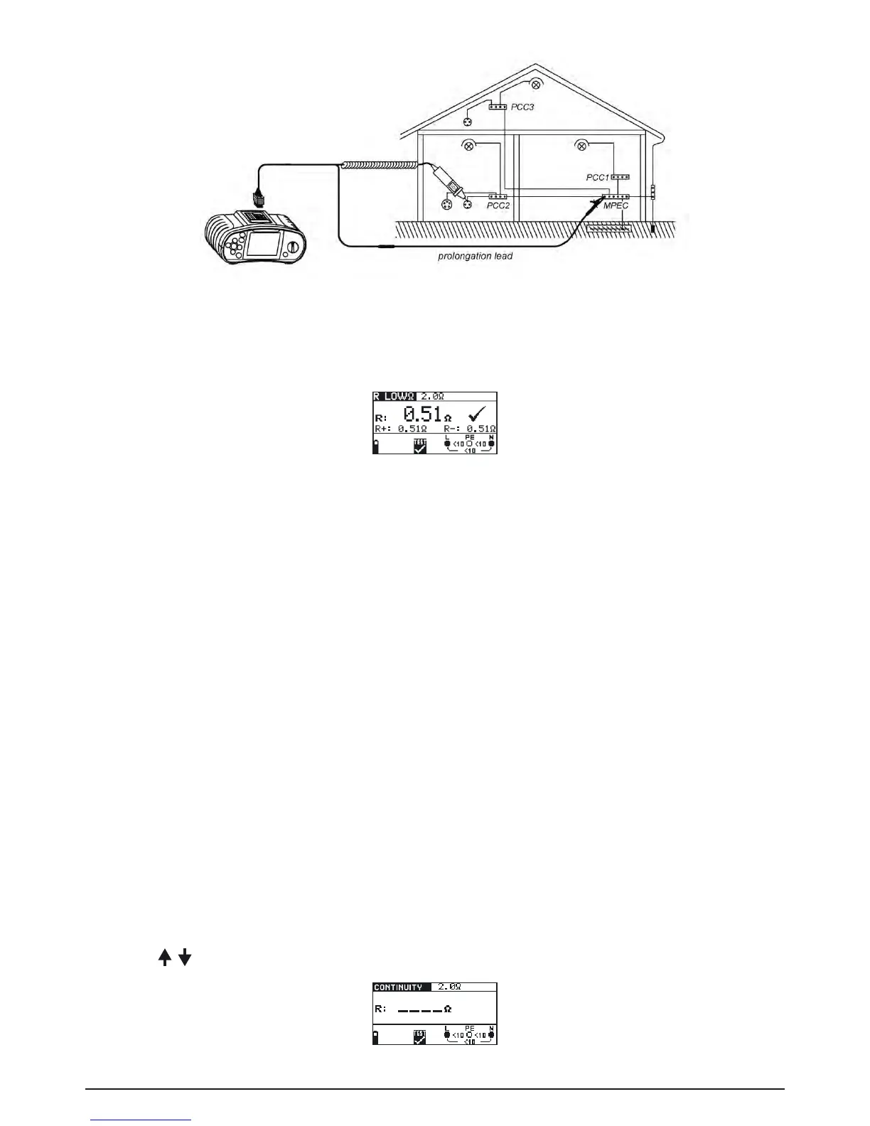
Fig. 5.7: Connection of tip commander and optional probe test lead (extension)
Step 5 Check the displayed warnings and online voltage/terminal monitor before starting mea-
surement. If OK, press the TEST key. After performing, the measurement results appear
on the display together with the PASS/FAIL indication (if applicable).
Fig. 5.8: Example of LowΩ resistance measurement results
Displayed results:
R: MainLowΩresistanceresult(averageofR+andR-results)
R+: LowΩresistancesub-resultwithpositivevoltageatLterminal
R-: LowΩresistancesub-resultwithpositivevoltageatNterminal.
Save displayed results for documentation purposes. Refer to chapter 6.1 for further information on
setting functions and saving of measurement results (BENNING IT 120 B only).
Warning:
- LowΩresistancemeasurementshouldonlybeperformedonde-energisedobjects!
- Parallelimpedancesortransientcurrentsmayinuencetestresults.
Note:
-
Ifvoltagebetweentestterminalsishigherthan10VtheRlowΩmeasurementwillnotbeperformed.
5.2.2 Continuity testing (CONTINUITY)
ContinuouslowΩresistancemeasurementisperformedwithoutpolereversalofthetestvoltage
andalowertestcurrent(fewmA).Ingeneral,thisfunctionservesasanordinaryΩ-meterwithlow-
test current. The function can also be used to test inductive components.
How to perform Continuity measurement:
Step 1 Select R
LOW
-Ω,DURCHGANG/ CONTINUITY with the function selector switch. Use the
/ keys to select the Continuity function. The following menu is displayed:
Fig. 5.9: Continuity measurement menu