45
5.9 Resistance to earth (R
E
) ( BENNING IT 120 B only)
The BENNING IT 120 B allows resistance to earth measurement using 3-wire measuring me-
thod (earthing set). Consider the following instructions when performing resistance to earth
measurement:
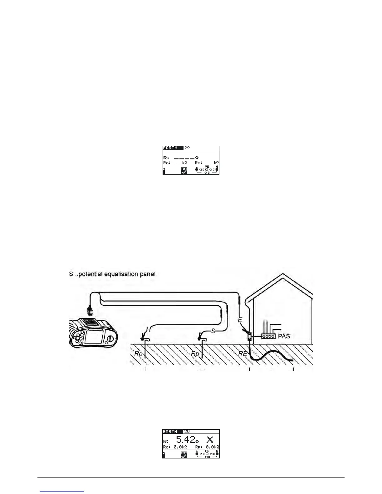
- The probe (S) is positioned between the earth electrode (E) and auxiliary earth electrode (H) in
theearthreferenceplane(seegure5.45).
- The distance from the earth electrode (E) to the auxiliary earth electrode (H) must be at least 5
timesthedepthorlengthoftheearthingelectroderod(seeg.5.45).
How to perform resistance to earth measurement:
Step 1 Select R
E
, ERDE/ EARTH function with the function selector switch. The following menu
is displayed:
Fig. 5.44: Earth resistance measurement menu
Connect the measuring cables to the BENNING IT 120 B.
Step 2 Set the following measuring parameters and limit values:
- High limit resistance value
Step 3 Followtheconnectiondiagramshowningure5.45toperformresistancetoearthmea-
surement. Use the Help function if necessary.
(Measuring cables: H = black, S = green, E = blue)
Fig. 5.45: Measurement with the earthing set – 20 m
Step 4 Check the displayed warnings and online voltage/terminal monitor before starting the
measurement. If OK, press the TEST key. After performing, the measurement results
appear on the display together with the PASS/FAIL indication (if applicable).
Fig. 5.46: Example of resistance to earth measurement results