75
Fault loop resistance
fault loop resistance both fault loops, R1 (L1-PE) and R2 (L2-PE)
prospective fault current I
SC1
and I
SC2
for both fault loops
Voltage, frequency symbols adapted to a power supply network with lower
voltage
Phase shift automatic recognition of three-phase mains
FI/RCD functions
contact voltage U
c
for both options, U1 (L1-PE) and U2 (L2-PE)
tripping time
maximum nominal differential current is limited to 1 Atripping current
automatic testing
Resistance to earth independent of the selected power supply network
PE conductor test key (TEST key) deactivated
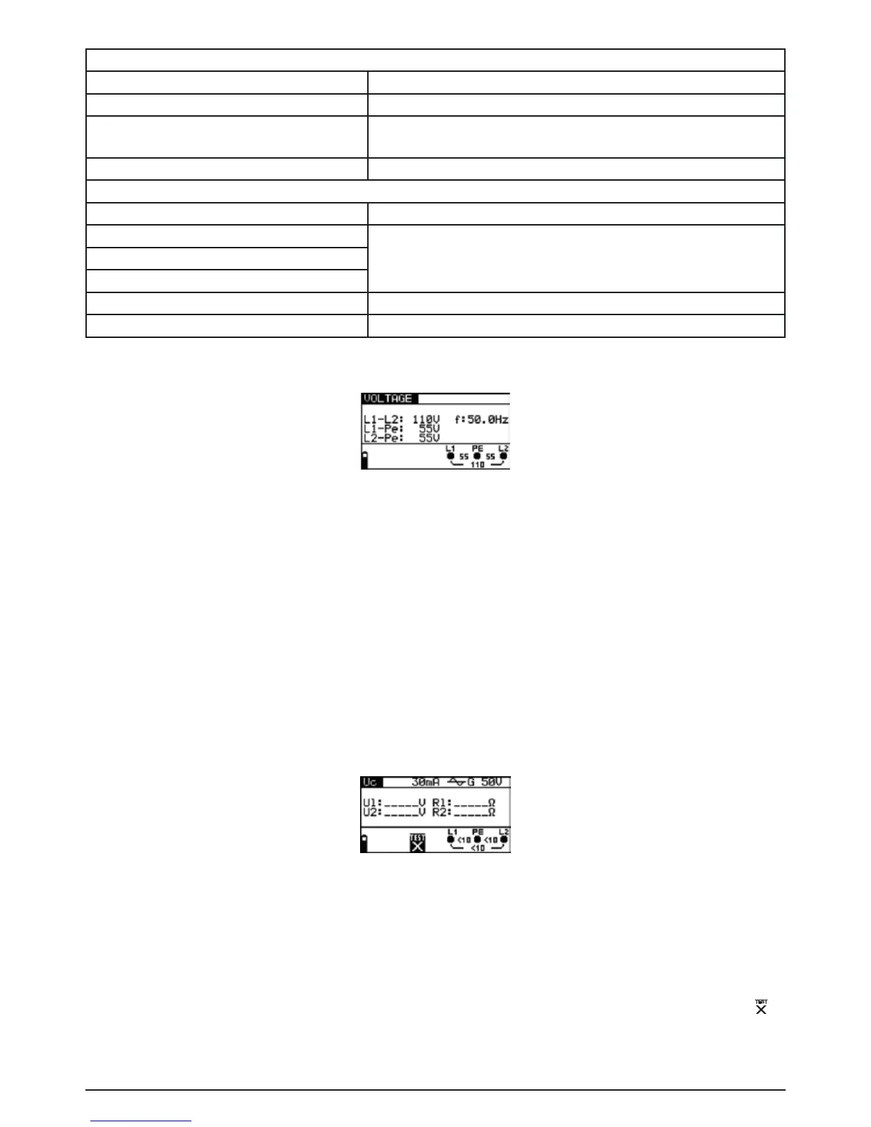
12.3.1 Voltage
Figure 12.2: Example of voltage and frequency measurements
Displayed results for a single-phase system:
L1-L2 voltage between external conductors,
L1-PE voltage between external conductor 1 and protective conductor,
L2-PE voltage between external conductor 2 and protective conductor.
12.3.2 FI/RCD testing
The normal maximum FI/RCD testing current is 1 A RMS (peak current 1.4 A) and can only be
reached,ifthefaultloopresistanceisbelow1Ω.
Tests are carried out automatically for both combinations (L1-PE and L2-PE).
For each individual test result, the corresponding indication is shown.
Figure 12.3: FI/RCD contact voltage test
12.3.3 Line resistance and prospective short-circuit current
The measured resistance represents the phase-to-phase resistance (R
L1-L2
). The nominal voltage
for calculating I
PSC
is set to 110 V.
The nominal voltage range for measuring the line resistance is 90 V to 121 V. If the input voltage
is outside this range, this is displayed on the online voltage/ terminal monitor together with the
symbol.