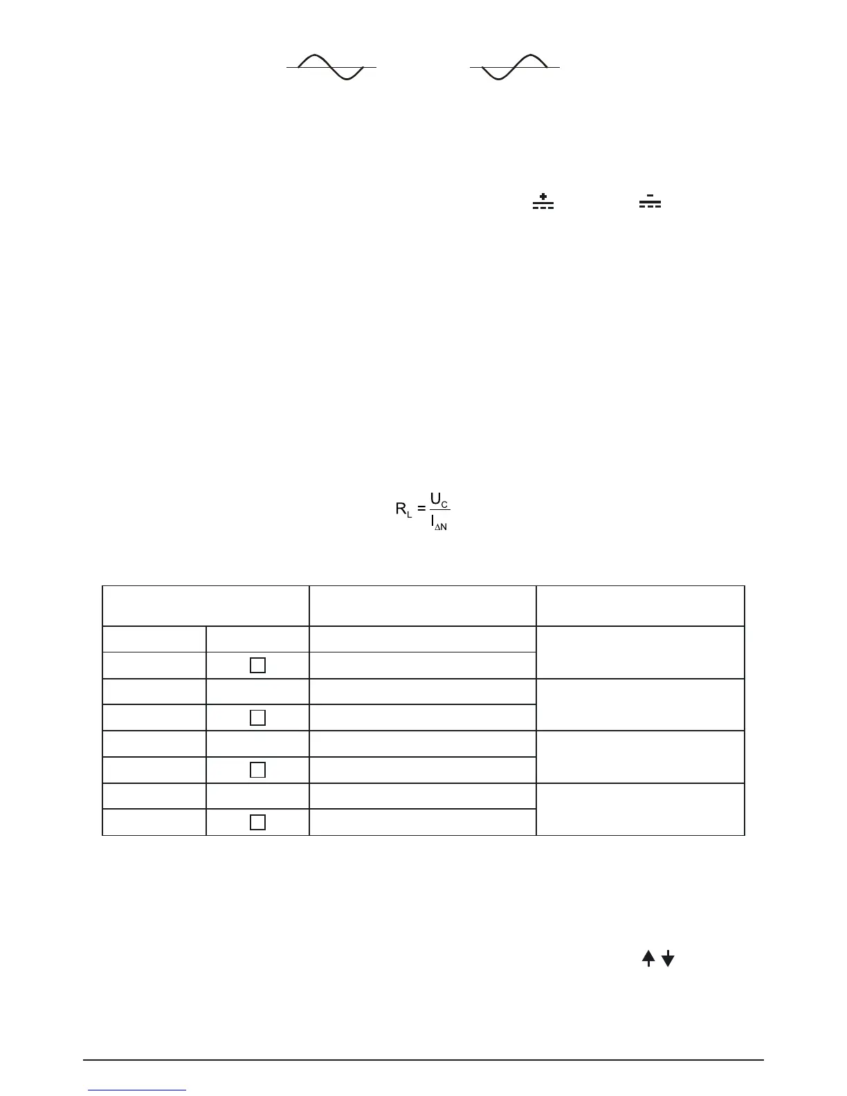
positive starting polarity
(0°)
negative starting polarity
(180°)
Fig. 5.13: Test current started with the positive or negative half-wave
For RCDs of type B, the fault current can be started with positive
or negative polarity.
During automatic testing (AUTO), the polarity is reversed automatically.
5.3.5 Testing selective (time-delayed) RCDs
SelectiveRCDsdemonstratedelayedresponsecharacteristics.Trip-outperformanceisinuenced
due to the pre-loading during measurement of contact voltage. In order to eliminate pre-loading a
time delay of 30 s is inserted before performing trip-out test.
5.3.6 Contact voltage (Uc)
LeakagecurrentowingtothePEterminalcausesavoltagedropacrossearthresistance,which
is called contact voltage. This voltage is present on all accessible parts connected to the PE termi-
nal and should be lower than the safety limit voltage.
The contact voltage is measured without tripping-out the RCD. R
L
is a fault loop resistance and is
calculated as follows:
Displayed contact voltage relates to the rated differential current of the RCD and is multiplied by a
safety factor. See the table 5.1 for detailed contact voltage calculation.
RCD type
Contact voltage Uc
proportional to
Nominal fault current I
∆N
AC G 1.05×I
∆N
Any
AC
S 2×1.05×I
∆N
A G 1.4×1.05×I
∆N
≥30mA
A
S 2×1.4×1.05×I
∆N
A G 2×1.05×I
∆N
< 30 mA
A
S 2×2×1.05×I
∆N
B G 2×1.05×I
∆N
Any
B
S 2×2×1.05×I
∆N
Table 5.1: Relationship between Uc and I
∆N
G = non-delayed fault current
S = time-delayed fault current (selective)
How to perform contact voltage measurement:
Step 1 Select FI/ RCD TEST (RCD) with the function selector switch. Use the / keys to se-
lect Uc (contact voltage).The following menu is displayed: