31
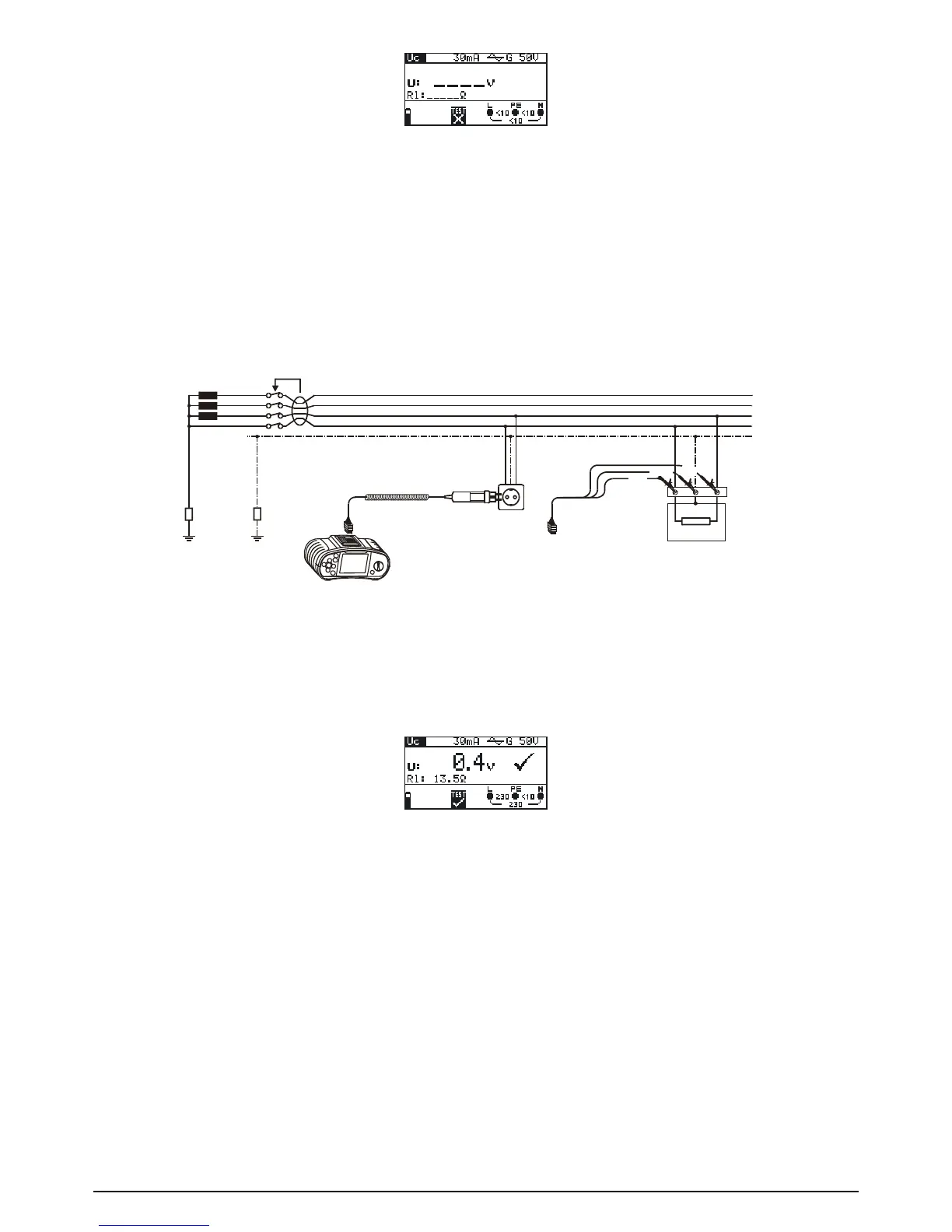
Fig. 5.14: Contact voltage measurement menu
Connect the test cable to the BENNING IT 110/ BENNING IT 120 B.
Step 2 Set the following measuring parameters and limit values:
- Nominal residual current
- RCD type
- Limit contact voltaget
Step 3 Followtheconnectiondiagramshowningure5.15toperformcontactvoltagemeasu-
rement. Use the Help function if necessary
Fig. 5.15: Connection of plug test cable or universal test cable
Step 4 Check the displayed warnings and online voltage/terminal monitor before starting the
measurement. If OK, press the TEST key. After performing, the measurement results
with PASS/FAIL indication appear on the display.
Fig. 5.16: Example of contact voltage measurement results
Displayed results:
U: Contact voltage
Rl: Loop impedance (fault loop resistance)
Save displayed results for documentation purposes. Refer to chapter 6.1 for further information on
setting functions and saving of measurement results. (BENNING IT 120 B only)
Note:
- Parameters set in this function are also kept for other RCD functions.
- The measurement of contact voltage does not normally trip an RCD. However, the trip limit may
beexceededasaresultofleakagecurrentowingtothePEprotectiveconductororviaaca-
pacitive connection between L and PE conductors.