42
Fig. 5.36: Phase sequence test menu
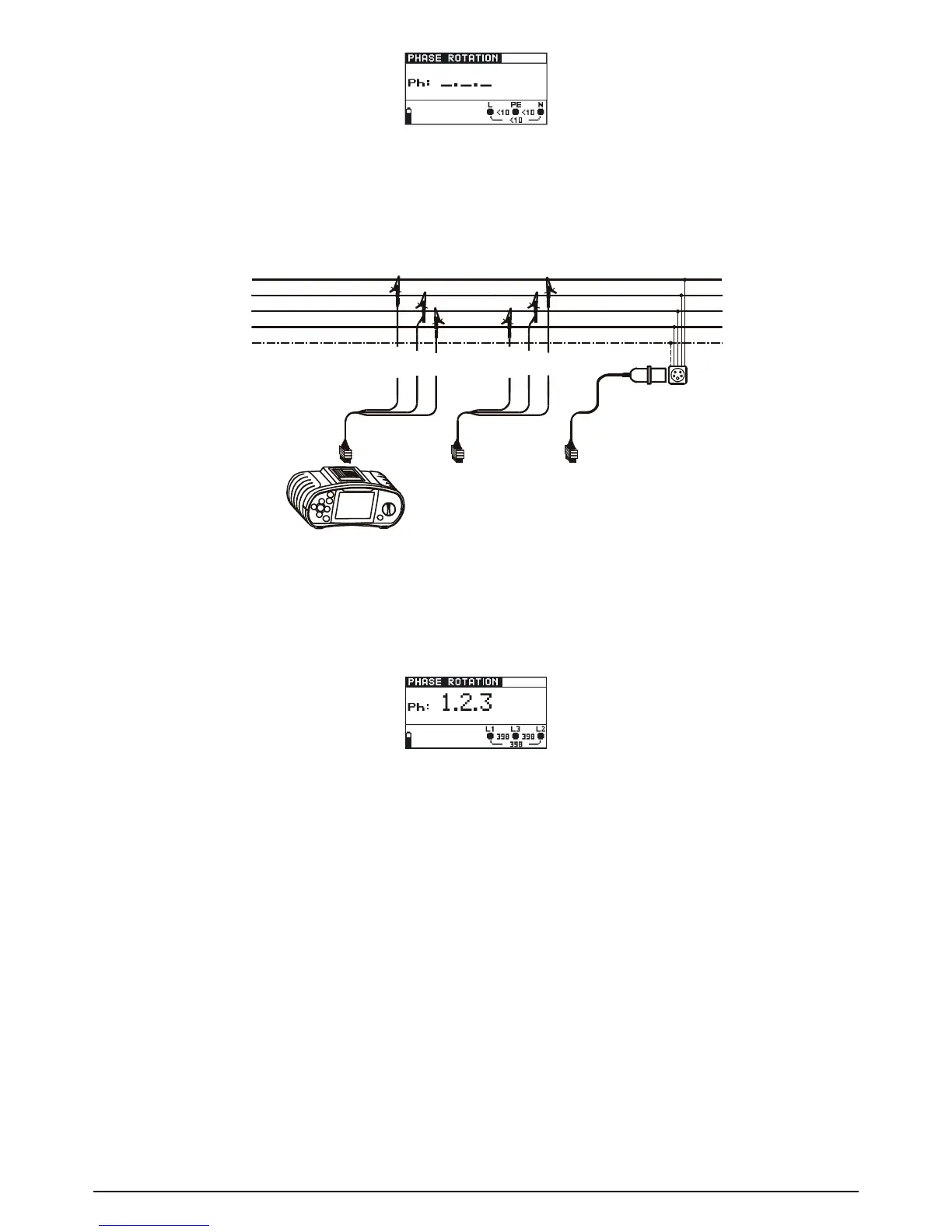
Connect the test cable to the BENNING IT 110/ BENNING IT 120 B
Step 2 Followtheconnectiondiagramshowningure5.37totestphasesequence.
Fig. 5.37: Connection of universal test cable and optional three phase cable
Step 3 Check the displayed warnings and online voltage/terminal monitor. Continuous test is
running. The actual result is shown on the display during the test. All three-phase volta-
ges are displayed in order of their sequence represented by the numbers 1, 2 and 3.
Fig. 5.38: Example of phase sequence test result
Displayed result:
Ph Phase sequence
1.2.3 Correct connection (clockwise phase rotation)
2.3.1 Wrong connection (anticlockwise phase rotation)
-.-.- Irregular voltages
Save displayed results for documentation purposes. Refer to chapter 6.1 for further information on
setting functions and saving of measurement results (BENNING IT 120 B only).
5.7 Voltage and frequency (V~)
How to perform voltage and frequency measurement:
Step 1 Select VOLTAGE V~ function with the function selector switch. The following menu is
displayed: