20
Fig. 4.3: Example of help menu
4.4 Setup menu
In the Setup menu the following actions can be taken:
- Supply system selection
- Prospective short/fault current scaling factor adjustment
- Language selection
- Communication port settings
- Activating/ deactivating the COMMANDER (switchable probe tip)
To enter the Setup menu press the backlight key
and rotate the function selector switch in any
direction at the same time.
Rotate function selector switch again to leave the Setup menu or setup sub-menus.
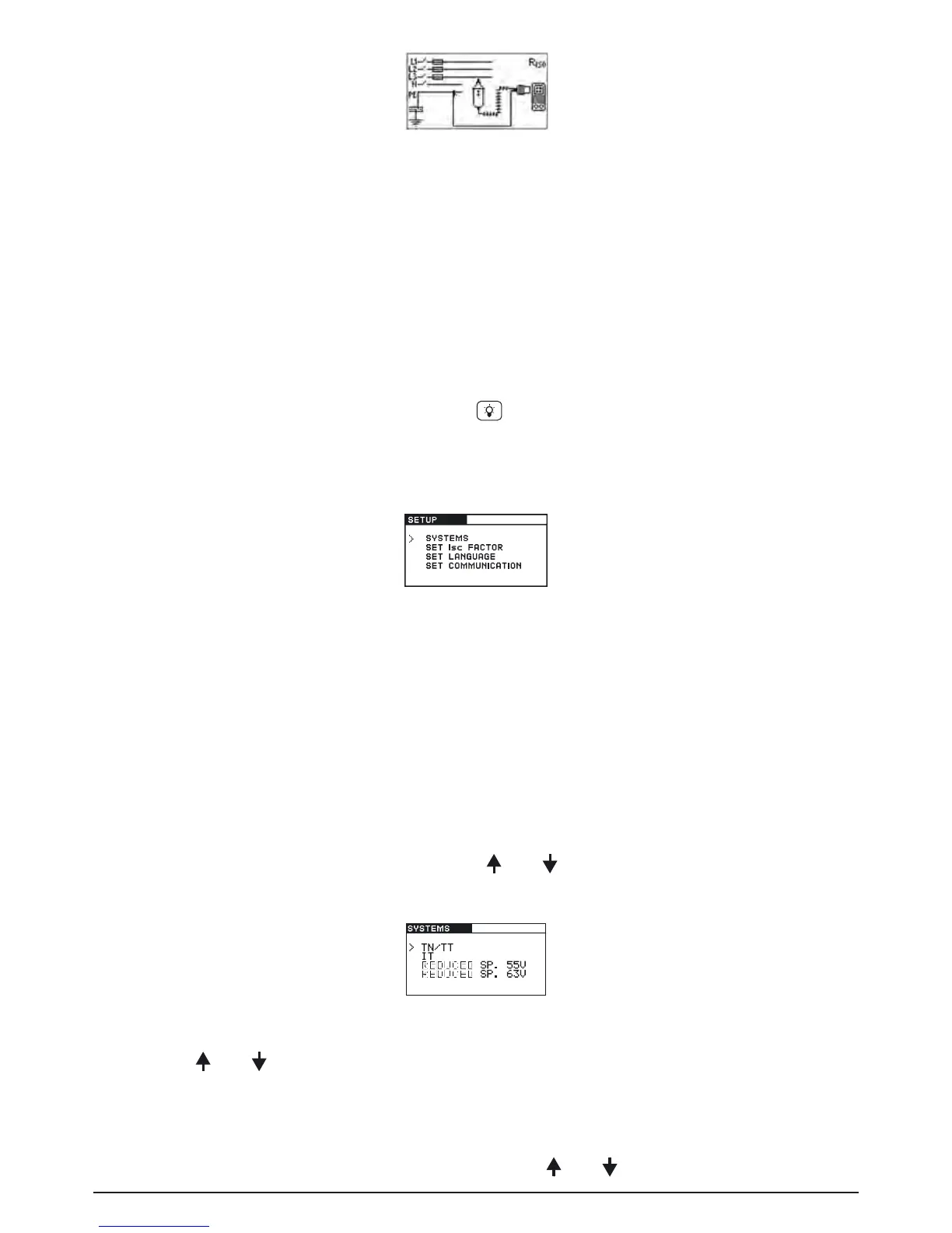
Fig. 4.4: Setup menu
4.4.1 Supply system setup
The BENNING IT 110/ BENNING IT 120 B enables tests and measurements in the following sup-
ply systems:
- TN (TT) system
- IT system
- Reduced low voltage system (2 x 55 V)
- Reduced low voltage system (3 x 63 V)
Select SYSTEMS in the Setup menu by using the and keys and press the TEST key to enter
the Supply system setup menu.
Fig. 4.5: Supply systems selecting menu
By using the and keys select the supply system and press the TEST key to accept the
setting.
4.4.2 Prospective short/fault current scaling factor adjustment
Select SET ISC FACTOR in the Setup menu by using the and keys and press the TEST key